Audi A6 Typ 4G: Infrared System
Infrared System, Calibrating
Special tools and workshop equipment required
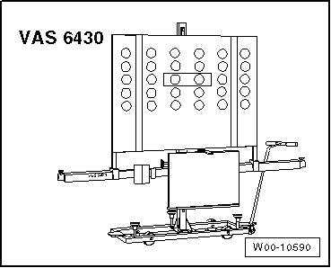
- Setting Device Basic Set -VAS6430/1- or Setting Device Basic Set -VAS 6430-
- Night Vision Calibration Tool -VAS6430/6-
- Calibration Tool - Linear Laser -VAS6350/3A- (can be used from the Calibration Tool -VAS 6350-)
- Vehicle Diagnostic Tester
- Wheel Alignment Computer
 Note
Note
- Make sure the Night Vision System Camera -R212- fits correctly in the bracket and the viewing range for the camera is not blocked.
- Make sure the protective window on the Night Vision System Camera -R212- is not chipped. Replace it if necessary. Refer to → Communication; Rep. Gr.91; Infrared System; Night Vision System Camera, Removing and Installing.
- If the vehicle has an adaptive cruise control and night vision system, then the night vision system must be adjusted/calibrated first and after that can the adaptive cruise control be adjusted.
- If the ACC Reflector Mirror - Audi -VAS6430/3- is located on the calibration beam of the Setting Device Basic Set -VAS6430/1-, it must be removed.
There Are Two Choices for Calibrating/Adjusting:
The "Quick Access"
This procedure should be selected for the following activities if only the calibration/adjustment will be performed.
- "No or incorrect basic setting/adaptation" is stored actively in the Diagnostic Trouble Code (DTC) memory.
- The camera was removed or replaced,
- The bumper or the radiator grille was removed or replaced,
The "Complete Alignment"
This procedure should be selected for the following activities if a calibration/adjustment and a suspension adjustment will be performed.
- Adjustments were made on the rear axle,
- Parts of the suspension were replaced on the vehicle.
Note
Both procedures are programmed into the axle alignment computer. The respective procedure is performed automatically. It is only necessary to select the appropriate program for the procedure that will be performed.
Preparation Work for Calibrating and Adjusting Driver Assist Systems. Refer to → Chapter "Preparation Work for Calibrating and Adjusting Driver Assist Systems".
Calibration procedure without a previous axle alignment
- Select the infrared system calibration procedure in the alignment computer.
- Attach the sensor according to the wheel alignment computer.
Calibrating/adjusting with a previous axle alignment
- Connect the battery charger. Refer to → Electrical Equipment; Rep. Gr.27; Battery; Battery, Charging.
- Position the front wheels so they are straight.
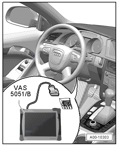
- Connect the Vehicle Diagnostic Tester to the vehicle and guide the diagnostic cable through the open window.
- Turn off all vehicle exterior lamps.
- Close all vehicle door.
Procedure for All
- Connect the Vehicle Diagnostic Tester to the vehicle and guide the diagnostic cable through the open window.
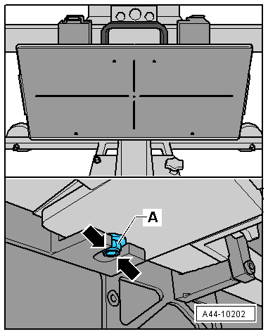
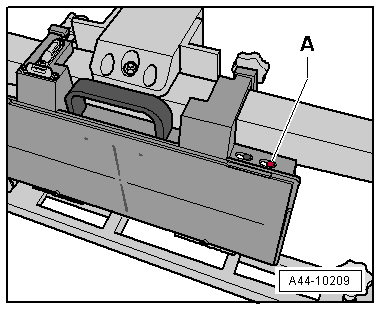
- Position the Night Vision Calibration Tool on the center of the calibration beam of the Setting Device Basic Set -VAS6430/1-.
- The opening -arrows- must surround the nut and bolt -A- when the Night Vision Calibration Tool is pushed onto the calibration beam.
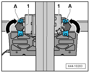
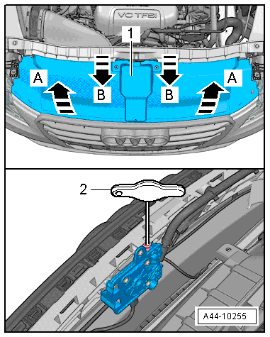
- Fold up the right and left bracket -A-.
- Tighten the right and left clamping screw -1- hand-tight.
- Set up the Setting Device Basic Set -VAS6430/1- and the Night Vision Calibration Tool in front of the vehicle.
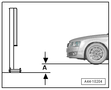
- Position the Night Vision Calibration Tool -VAS6430/6- in distance -A- to the infrared camera.
Note
Distance -A- = 120 cm +- 2.5 cm, measured between the Night Vision Calibration Tool -VAS6430/6- and the lens on the Night Vision System Camera -R212-.
- Attach the measuring sensor for the front wheels to the calibration beam.
- For the following work steps, the hoist must be in the lowest position -A-.
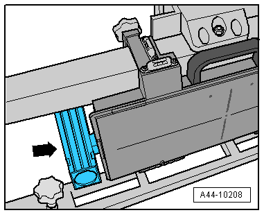
- Install and secure the Calibration Tool - Linear Laser -VAS6350/3--arrow- into the guide in the Night Vision Calibration Tool.
- Switch on the Calibration Tool - Linear Laser -VAS6350/3-. A laser beam is beamed on the vehicle.
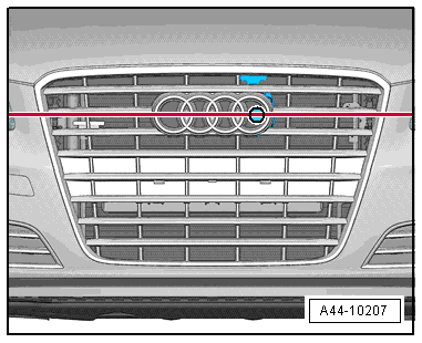
- Turn the lever on the back of the calibration board to align the laser beam so that it is in the center of the camera lens in the horizontal position.
The specified height is now reached and the Linear Laser -VAS6350/3A- can be switched off.
- Level the bubble level -A- using the adjusting screw -1-.
The bubble adjustment -A- serves to compare the ground conditions.
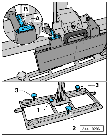
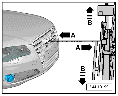
- Move the Setting Device Basic Set -VAS6430/1- sideways -arrow B- until the display on the alignment computer is within the tolerance range.
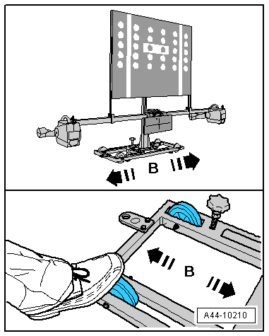
- Secure the Setting Device Basic Set -VAS6430/1- by tightening the bolts -2- and -3- slightly. (This prevents the Setting Device Basic Set -VAS 6430- from rolling away).

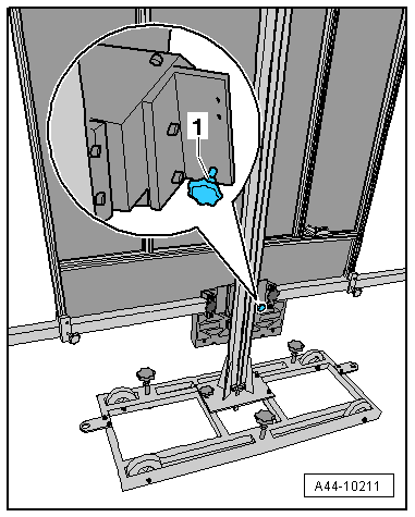
- Turn the precision adjustment screw -1- on the calibration beam until the display on the alignment computer is located within the tolerance range.
- Level the bubble level -A- using the adjusting screw -1-.
- Level the bubble level -B- using the adjusting screw -2-.
- Turn the Calibration Tool - Linear Laser -VAS6350/3- back on and check the specified height and correct if necessary. A laser beam is beamed on the vehicle.
- Turn the lever on the back of the calibration board to align the laser beam so that it is in the center of the camera lens in the horizontal position.
The specified height is now reached and the Linear Laser -VAS6350/3A- can be switched off.
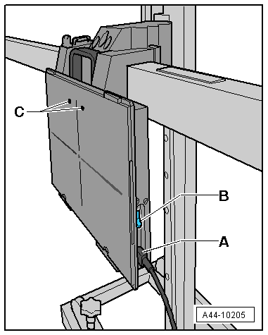
- Connect the network connector -A- from the Night Vision Assist Calibration and Adjust Tool to the current network.
- Turn on the switch -B- on the Night Vision Assist Calibration and Adjust Tool.
Note
An internal initialization takes place after switching on the Infrared System Calibration Plate. Both LEDs -C- blink at the same time and an acoustic tone will sound if the initialization is successful and was performed without any faults. After this, the Infrared System Calibration Plate is in the ready mode. The green LED will blink slowly.
Note
Check the bubble level and correct the adjustment if necessary.
- Push the button -A- to activate the heating function.
An acoustic signal will sound when the heating function is activated. The heat-up phase has begun.
As soon as the specified temperature is reached, the green LED will stay on.
The heating elements switch off automatically after 20 minutes. An acoustic signal will sound approximately 1 minute before the heating elements switch off automatically.
Press the button -A- at any time to reset the timer back to 20 minutes. An short acoustic signal confirms that it has be reset.
Perform any subsequent work using the Vehicle Diagnostic Tester.
- Connect the Vehicle Diagnostic Tester and proceed with a vehicle-specific entry in Guided Fault Finding.
Wait until the Vehicle Diagnostic Tester has checked all the vehicle control module.
- Press the GO TO button and select "function/component selection".
- Select the program in Guided Functions.
Follow the instructions on the screen of the Vehicle Diagnostic Tester to perform the adjustment/calibration.
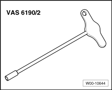
Turn the adjusting screw with a hex socket wrench (minimum length: approximately 120 mm) to mechanically adjust the Night Vision System Camera -R212- around its roller axle.
- To do so open the hood and remove the lock carrier cover -1-. Refer to → Body Exterior; Rep. Gr.63; Front Bumper; Overview - Bumper Cover.
- Mount the hex socket wrench -2- and make the adjustment according to the specification in "Guided Fault Finding".
Note
Make sure there is no one or nothing between the Night Vision System Camera -R212- and the infrared system calibration plate while making the adjustment.
Adjusting the pitch-yaw angle of the Night Vision System Camera -R212- is electronic by starting the correct program using the Vehicle Diagnostic Tester in Guided Functions.
Special Tools
Special tools and workshop equipment required
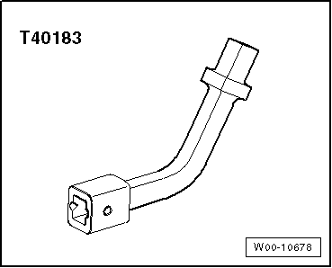
- Track Rod Tool Insert -T40183-
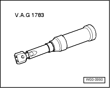
- Torque Wrench 1783 - 2-10Nm -VAG1783-
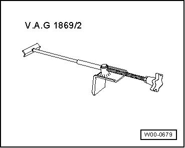
- Brake Pedal Actuator -VAG1869/2-.
- ACC Adjuster -VAS6190/2-
- Setting Device Basic Set -VAS6430/1-
- ACC Reflector Mirror - Audi -VAS6430/3-
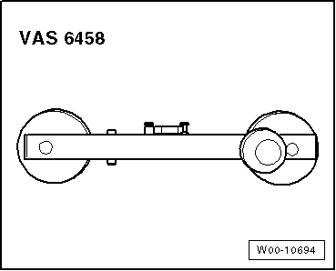
- Steering Wheel Scales -VAS6458-