Audi A6 Typ 4G (2011–2018) Workshop Manual / Chassis / Suspension, Wheels, Steering / Steering / Overview - Steering Column
Audi A6 Typ 4G: Overview - Steering Column
Overview - Steering Column, Manual
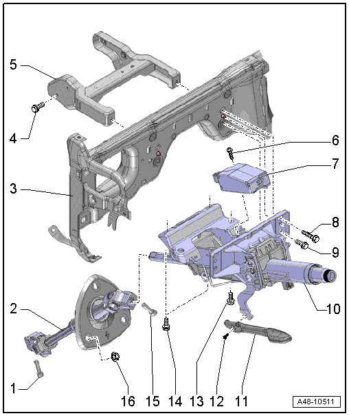
1 - Bolt
- 30 Nm
- Always replace if removed
- The threaded hole for the bolt must always be cleaned (for example, using a thread tap).
- Install the bolt first, then pull on the steering intermediate shaft several time to make sure it is secure. Tighten the bolt.
2 - Steering Intermediate Shaft
- Removing and installing. Refer to → Chapter "Steering Intermediate Shaft, Removing and Installing".
- Pay attention to the installed position of the sealing boot
3 - Central Tube
4 - Bolt
- Tightening specification. Refer to → Body Interior; Rep. Gr.70; Instrument Panel Central Tube; Overview - Instrument Panel Central Tube.
5 - Bracket
- Removing and installing. Refer to → Body Interior; Rep. Gr.70; Instrument Panel Central Tube; Mounting Bracket, Removing and Installing.
6 - Bolt
- 5 Nm
7 - Electronic Steering Column Lock Control Module -J764-
- Installed on vehicles with lock lock-up system
- Removing and installing. Refer to → Chapter "Electronic Steering Column Lock Control Module -J764-, Removing and Installing".
- If the control module is being replaced, then select "replace" control module on the Vehicle Diagnostic Tester in Guided Functions.
8 - Bolt
- 20 Nm
- Quantity: 2
- Follow the assembly sequence when installing.
9 - Bolt
- 20 Nm
- Quantity: 2
- Follow the assembly sequence when installing.
10 - Steering Column
- There are different versions. For the correct allocation. Refer to the Parts Catalog.
- Calibrate after replacing the steering column on a vehicle with dynamic steering. Refer to → Chapter "Dynamic Steering Basic Setting".
- Removing and installing. Refer to → Chapter "Steering Column, Removing and Installing".
- Check for damage. Refer to → Chapter "Steering Column, Checking for Damage".
11 - Handle
12 - Bolt
- 5 Nm
13 - Bolt
- For attaching the pedal assembly
- Tightening specification. Refer to → Brake System; Rep. Gr.46.
14 - Bolt
- 20 Nm
- Quantity: 2
- Follow the assembly sequence when installing.
15 - Bolt
- 30 Nm
- Always replace if removed
- The threaded hole for the bolt must always be cleaned (for example, using a thread tap).
16 - Nut
- 3 Nm
Overview - Steering Column, Power
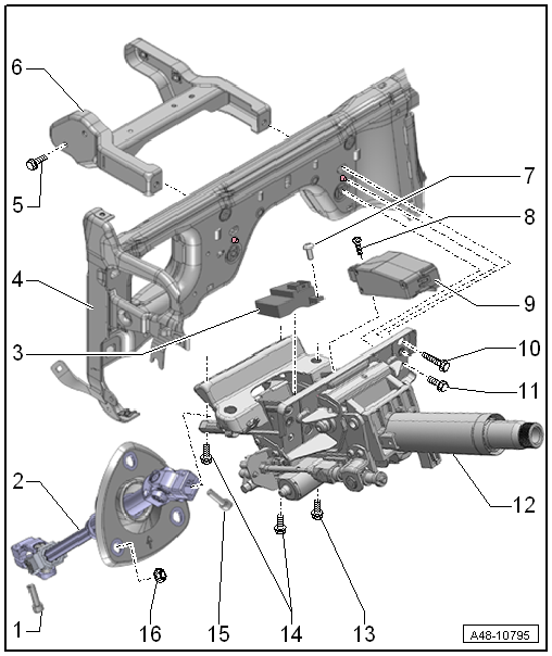
1 - Bolt
- 30 Nm
- Always replace if removed
- The threaded hole for the bolt must always be cleaned (for example, using a thread tap).
- Install the bolt first, then pull on the steering intermediate shaft several time to make sure it is secure. Tighten the bolt.
2 - Steering Intermediate Shaft
- Removing and installing. Refer to → Chapter "Steering Intermediate Shaft, Removing and Installing".
- Pay attention to the installed position of the sealing boot
3 - Power Adjustable Steering Column Control Module -J866-
- Removing and installing. Refer to → Chapter "Power Adjustable Steering Column Control Module -J866-, Removing and Installing".
4 - Central Tube
5 - Bolt
- Tightening specification. Refer to → Body Interior; Rep. Gr.70; Instrument Panel Central Tube; Overview - Instrument Panel Central Tube.
6 - Bracket
- Removing and installing. Refer to → Body Interior; Rep. Gr.70; Instrument Panel Central Tube; Mounting Bracket, Removing and Installing.
7 - Bolt
- 5 Nm
8 - Bolt
- 5 Nm
- 9 - Electronic Steering Column Lock Control Module -J764-
- Removing and installing. Refer to → Chapter "Electronic Steering Column Lock Control Module -J764-, Removing and Installing".
- Installed on vehicles with lock lock-up system
- If the control module is being replaced, then select "replace" control module on the Vehicle Diagnostic Tester in Guided Functions.
10 - Bolt
- 20 Nm
- Quantity: 2
- Follow the assembly sequence when installing.
11 - Bolt
- 20 Nm
- Quantity: 2
- Follow the assembly sequence when installing.
12 - Steering Column
- There are different versions. For the correct allocation. Refer to the Parts Catalog.
- Calibrate after replacing the steering column on a vehicle with dynamic steering. Refer to → Chapter "Dynamic Steering Basic Setting".
- Removing and installing. Refer to → Chapter "Steering Column, Removing and Installing".
- Check for damage. Refer to → Chapter "Steering Column, Checking for Damage".
13 - Bolt
- For attaching the pedal assembly
- Tightening specification.
14 - Bolt
- 20 Nm
- Quantity: 2
- Follow the assembly sequence when installing.
15 - Bolt
- 30 Nm
- Always replace if removed
- The threaded hole for the bolt must always be cleaned (for example, using a thread tap).
16 - Nut
- 3 Nm
