Audi A6 Typ 4G: Instrument Cluster
Overview - Instrument Cluster
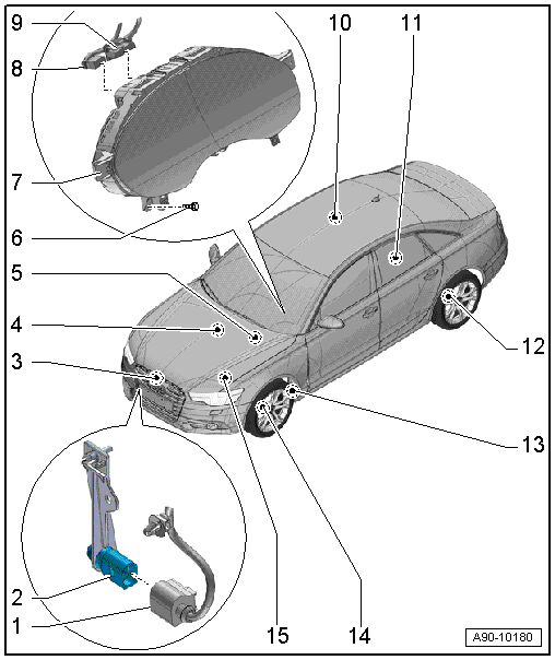
1 - Connector
- For Outside Air Temperature Sensor -G17-
2 - Outside Air Temperature Sensor -G17-
- Removing and installing. Refer to → Chapter "Outside Air Temperature Sensor, Removing and Installing".
3 - Oil Level Thermal Sensor -G266-
- Removing and installing. Refer to → Rep. Gr.17; Oil Pan/Oil Pump; Oil Level Thermal Sensor G266, Removing and Installing.
4 - Oil Pressure Switch -F22-/Reduced Oil Pressure Switch -F378-
- Removing and installing. Refer to → Rep. Gr.17; Oil Filter/Oil Pressure Switch; Overview - Oil Filter Housing/Oil Pressure Switch.
5 - Brake Fluid Level Warning Switch -F34-
- Removing and installing. Refer to → Brake System; Rep. Gr.47; Brake Booster/Master Brake Cylinder; Overview - Brake Booster/Master Brake Cylinder.
6 - Screw
- 3 Nm
- Quantity: 2
7 - Instrument Cluster
- With Instrument Cluster Control Module -J285-
- Removing and installing. Refer to → Chapter "Instrument Cluster with Instrument Cluster Control Module -J285-, Removing and Installing".
- Multi-pin connector pin assignment. Refer to → Chapter "Instrument Cluster Multi-Pin Connector Contact Assignment".
8 - Fiber Optic Cable Connector
- Seal with Fiber-Optic Repair Set - Connector Protective Caps -VAS6223/9-
9 - Connector
- For instrument cluster
10 - Fuel Level Sensor -G-
- Connector assignment. Refer to → Chapter "Fuel Level Sensor -G- Connector Assignment".
11 - Fuel Level Sensor 2 -G169-
- Connector assignment. Refer to → Chapter "Fuel Level Sensor 2 -G169- Connector Assignment".
12 - Rear Brake Pad Wear Sensor
- Left Rear Brake Pad Wear Sensor -G36-, Right Rear Brake Pad Wear Sensor -G37-
- Removing and installing. Refer to → Brake System; Rep. Gr.46.
13 - Windshield Washer Fluid Level Sensor -G33-
- Removing and installing. Refer to → Chapter "Windshield Washer Fluid Level Sensor, Removing and Installing".
14 - Front Brake Pad Wear Sensor
- Left Front Brake Pad Wear Sensor -G34-, Right Front Brake Pad Wear Sensor -G35-
- Removing and installing. Refer to → Brake System; Rep. Gr.46.
15 - Engine Coolant Level Warning Switch -F66-
Overview - Windshield Projection Head Up Display
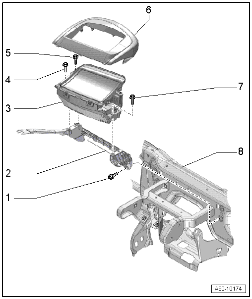
1 - Screw
- Quantity: 4
- Tightening specification. Refer to → Body Interior; Rep. Gr.70; Instrument Panel Central Tube; Overview - Instrument Panel Central Tube.
2 - Bracket
- For windshield projection control module
- Removing and installing. Refer to → Body Interior; Rep. Gr.70; Instrument Panel Central Tube; Overview - Instrument Panel Central Tube
3 - Windshield Projection Head Up Display Control Module -J898-
- Removing and installing. Refer to → Chapter "Windshield Projection Head Up Display Control Module, Removing and Installing".
- Calibrating. Refer to → Chapter "Windshield Projection Head Up Display Control Module, Calibrating".
4 - Screw
- 5.5 Nm
5 - Screw
- 5.5 Nm
6 - Upper Cover
- Removing and installing. Refer to → Body Interior; Rep. Gr.70; Instrument Panel; Overview - Instrument Panel
7 - Screw
- 5.5 Nm
8 - Central Tube
Instrument Cluster with Instrument Cluster Control Module -J285-, Removing and Installing
Special tools and workshop equipment required
- Fiber-Optic Repair Set - Connector Protective Caps -VAS6223/9- from Fiber-Optic Repair Set -VAS6223B-
 Note
Note
- All warning lamps in instrument cluster are fitted with light-emitting diodes. In case an indicator lamp is malfunctioning, the instrument cluster must be replaced.
- Do not disassemble the instrument cluster.
- It is not necessary to remove the steering wheel in order to remove the instrument cluster.
- If the instrument cluster with the Instrument Cluster Control Module -J285- was replaced, select the "Replace" function for the corresponding control module in the "Guided Fault Finding" or "Guided Functions" operating mode using the Vehicle Diagnostic Tester.
Removing
- Adjust steering wheel downward and to rear as far as possible, use entire adjustment range of steering column adjustment for this.
- Remove the light switch. Refer to → Chapter "Light Switch -E1-, Removing and Installing".
- Remove the instrument cluster frame. Refer to → Body Interior; Rep. Gr.70; Instrument Panel; Instrument Cluster Frame, Removing and Installing.
- Remove the bolts -1 and 3-.
- Pull the instrument cluster -2- out just far enough until it is touching the steering wheel.
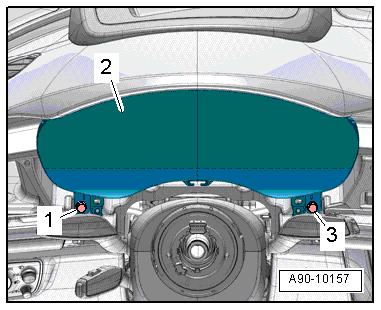
- Disconnect the connector -2- for the fiber-optic cable and the connector -1-.
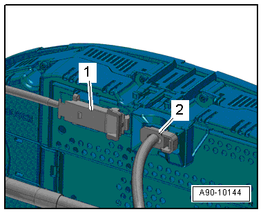
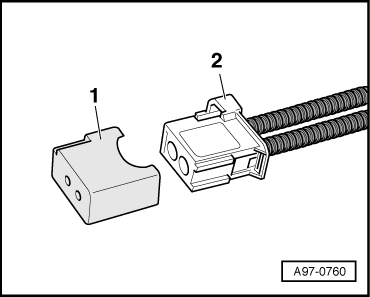
- Seal open wiring harness connector -2- with Fiber-Optic Repair Set - Connector Protective Caps - VAS6223/9--item 1-.
Note
The protective cap prevents contamination of or mechanical damage to end face of fiber optic cable which would impair signal transmission.
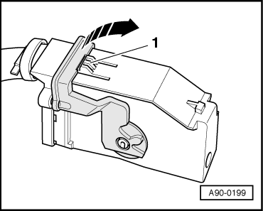
- To disconnect the connector, press the tab -1-, turn the retaining bracket in direction of the -arrow- and remove the connector.
- Remove the instrument cluster on the front passenger side between the steering wheel and the instrument panel.
Installing
Install in reverse order of removal. Note the following:
- Follow the instructions on the Vehicle Diagnostic Tester display with a new instrument cluster.
Instrument Cluster Multi-Pin Connector Contact Assignment
Gray 32-pin connector -A-
1 - MOST bus ring break diagnosis
2 - Not Assigned
3 - CAN bus instrument cluster low
4 - CAN bus instrument cluster high
5 - Fuel tank sensor ground
6 - Fuel Level Sensor -G-
7 - Fuel Level Sensor -G-
8 - Display Unit Button -E506- (Reset Button)
9 - Fuel Level Sensor 2 -G169-
10 - Fuel Level Sensor 2 -G169-
11 - Not Assigned
12 - Not Assigned
13 - Not Assigned
14 - Not Assigned
15 - Not Assigned
16 - Not Assigned
17 - Not Assigned
18 - Not Assigned
19 - Night Vision System Control Module -J853-"-"
20 - Night Vision System Control Module -J853-"+"
21 - Not Assigned
22 - Not Assigned
23 - Not Assigned
24 - Not Assigned
25 - Not Assigned
26 - Not Assigned
27 - Not Assigned
28 - Not Assigned
29 - Terminal 31
30 - Terminal 31
31 - Terminal 30
32 - Terminal 30
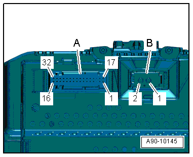
Optical MOST-Bus connection (fiber optic) -B-
1 - MOST bus input
2 - MOST bus output
Fuel Level Sensor Connector Assignment
Fuel Level Sensor -G- Connector Assignment
Disconnect the connector on the fuel tank locking flange. For the procedure. Refer to → Rep. Gr.20; Fuel Delivery Unit/Fuel Level Sensor; Fuel Level Sensor G, Removing and Installing.
Note
Check the exact connector assignment in the current wiring diagram → Wiring diagrams, Troubleshooting & Component locations.
Fuel Level Sensor 2 -G169- Connector Assignment
Disconnect the connector on the fuel tank locking flange. For the procedure. Refer to → Rep. Gr.20; Fuel Delivery Unit/Fuel Level Sensor; Fuel Level Sensor 2 G169, Removing and Installing.
Note
Check the exact connector assignment in the current wiring diagram → Wiring diagrams, Troubleshooting & Component locations.
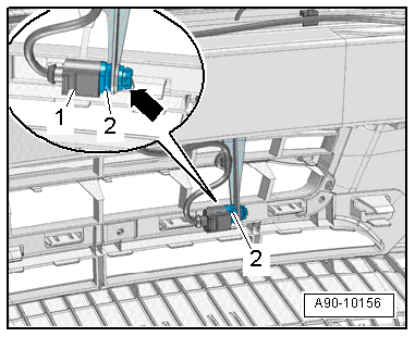
Outside Air Temperature Sensor, Removing and Installing
Removing
- Remove the lock carrier cover. Refer to → Body Exterior; Rep. Gr.63; Front Bumper; Attachments, Removing and Installing.
- Squeeze the clips carefully -arrow- and remove the Outside Air Temperature Sensor -G17--item 2-.
- Disconnect the connector -1-.
Installing
Install in reverse order of removal. Note the following:
After completing the repair, perform the following on the Front A/C Display Control Head -E87- in the "Guided Fault Finding" function using the Vehicle Diagnostic Tester:
- Read the DTC memory and erase any entries.
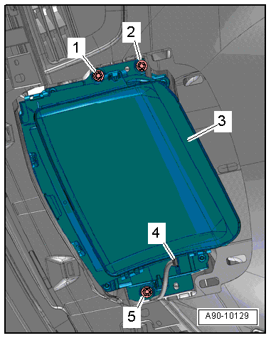
Windshield Projection Head Up Display Control Module, Removing and Installing
 Caution
Danger of causing damage.
- Remove only the marked screws from the Windshield Projection Head Up Display Control Module -J898-.
- The Windshield Projection Head Up Display Control Module -J898- must be replaced if the screws are removed from the housing upper section.
- If the Windshield Projection Head Up Display Control Module -J898- should fall down, it must be replaced because the inner components will get damaged even though there is no damage on the outside.
- Do not place any force on the upper section of the Windshield Projection Head Up Display Control Module -J898- housing. Otherwise the Windshield Projection Head Up Display Control Module -J898- will have to be replaced.
Removing
- Remove the windshield projection control module cover. Refer to → Body Interior; Rep. Gr.70; Instrument Panel; Overview - Instrument Panel.
- Cover the control module -3- with a soft towel.
- Remove the windshield. Refer to → Body Exterior; Rep. Gr.64; Windshield; Windshield, Removing and Installing.
- Remove the bolts -1, 2 and 5-.
- Lift the control module slightly and disconnect the connector -4-.
- Remove the control module.
Installing
Install in reverse order of removal. Note the following:
- Install the control module and tighten the screws.
- Mount the windshield and secure it - do not bond it.
- Turn on the ignition and check the control module function.
- A number must be appear on the windshield.
- Calibrate the windshield projection control module. Refer to → Chapter "Windshield Projection Head Up Display Control Module, Calibrating".
Windshield Projection Head Up Display Control Module, Calibrating
Special tools and workshop equipment required
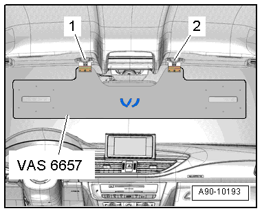
- Head-Up Display Calibration Board - Audi A6 -VAS6657-
- Calibration Board - Head-Up Display -VAS6658-
Conditions
- The windshield projection control module must be calibrated during the following conditions:
- The Windshield Projection Head Up Display Control Module -J898- was replaced.
- The windshield was removed and installed.
- The DTC "no or incorrect basic setting/adaptation" is stored in the DTC memory.
Procedure
- Move the vehicle onto a secure flat surface.
- Set the parking brake - the vehicle must not move during the measuring.
- Remove the windshield projection control module cover. Refer to → Body Interior; Rep. Gr.70; Instrument Panel; Overview - Instrument Panel.
- Fold down the left and right sun visors, disengage them and move them to the side.
- Engage the Calibration Board - Head-Up Display -VAS6658- to the center support -1 and 2- for the sun visor.
Performing Calibration
Vehicle Diagnostic Tester is attached.
- Select the Diagnostic mode and start the diagnostics.
- Select the tab test plan.
- Select select individual tests and choose the following sequence.
- Body
- Electrical Equipment
- 01 - OBD-capable systems
- 82 - Windshield Projection Head Up Display Control Module - J898
- 82 - windshield projection control module, function
- 82 - calibrating the head up display
From here using the Vehicle Diagnostic Tester advances the calibration procedure forward.
- After calibrating the windshield projection head up control module successfully, end "calibration", turn off the ignition and disconnect the diagnostic connector.