Audi A6 Typ 4G: Seat Angle Adjuster, Removing and Installing
Seat Angle Adjuster, Removing and Installing
Removing
 WARNING
- Follow all Safety Precautions when working with pyrotechnic components. Refer to → Chapter "Pyrotechnic Components Safety Precautions".
- Before handling pyrotechnic components (for example, disconnecting the connector), the person handling it must "discharge static electricity". This can be done by touching the door striker, for example.
- Remove the front seat. Refer to → Chapter "Front Seat, Removing and Installing".
- Fasten the front seat on the Engine/Transmission Holder - Seat Repair Fixture -VAS6136-. Refer to → Chapter "Front Seat, Mounting on Fixture for Seat Repair".
- Remove the trim on the sill side. Refer to → Chapter "Seat Side Trim on Sill Panel Side, Removing and Installing, Front Seat (Manual)".
- Remove the handle from the seat angle adjuster. Refer to → Chapter "Seat Angle Adjustment Handle, Removing and Installing".
- Remove the step pin -2- and bolt -3-.
- Remove the seat angle adjuster -1-.
Installing
WARNING
- Follow all Safety Precautions when working with pyrotechnic components. Refer to → Chapter "Pyrotechnic Components Safety Precautions".
- Before handling pyrotechnic components (for example, connecting the connector), the person handling it must "discharge static electricity". This can be done by touching the door striker, for example.
Install in reverse order of removal. Note the following:
 Note
Note
Make sure the connectors are installed correctly and are secure.
WARNING
Ignition must be on when connecting battery. If pyrotechnic components (for example, airbag, belt tensioner) are not repaired correctly, they may deploy unintentionally after connecting battery. There must not be anyone inside the vehicle when connecting the battery.
DANGER!
When working on vehicles with the ignition already switched on or that are ready to drive there is a danger of the engine starting unexpectedly and of being poisoned by gas in enclosed areas. Risk of body parts and/or clothing being clamped or pulled.
Perform the following before switching on the ignition:
- Move the selector lever into P.
- Activate the parking brake
- Turn off the ignition.
- Open the hood
- Connect the charger, such as the Battery Charger -VAS5095A- to the jump start of the 12V vehicle electrical system.
- Turn on the ignition.
- Connect the battery GND cable with the ignition turned on. Refer to → Electrical Equipment; Rep. Gr.27; Battery; Battery, Disconnecting and Connecting.
Note
If the Airbag Indicator Lamp -K75- indicates a fault, check the Diagnostic Trouble Code (DTC) memory, erase it and check it again. Refer to Vehicle Diagnostic Tester.
Installation notes, for example tightening specifications, replacing components. Refer to → Chapter "Overview - Seat Pan, Seat Angle Adjuster".
Seat Angle Adjustment Motor, Removing and Installing
Removing
WARNING
- Follow all Safety Precautions when working with pyrotechnic components. Refer to → Chapter "Pyrotechnic Components Safety Precautions".
- Before handling pyrotechnic components (for example, disconnecting the connector), the person handling it must "discharge static electricity". This can be done by touching the door striker, for example.
- Remove the front seat. Refer to → Chapter "Front Seat, Removing and Installing".
- Fasten the front seat on the Engine/Transmission Holder - Seat Repair Fixture -VAS6136-. Refer to → Chapter "Front Seat, Mounting on Fixture for Seat Repair".
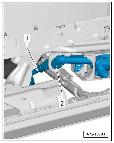
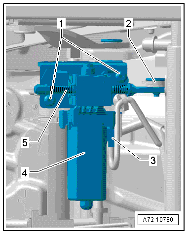
- Remove bolt -2- for seat angle adjustment motor (preset by the manufacturer) adjusting spindle -1-.
 Caution
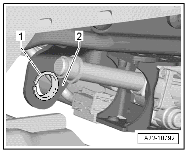
Risk of damage to the bushing -1- in the bearing point -2- (adjusting spindle/seat pan bolting).
- The bushing cannot be replaced with shop materials.
- If the bushing is damaged, the corresponding assembly parts must be replaced.
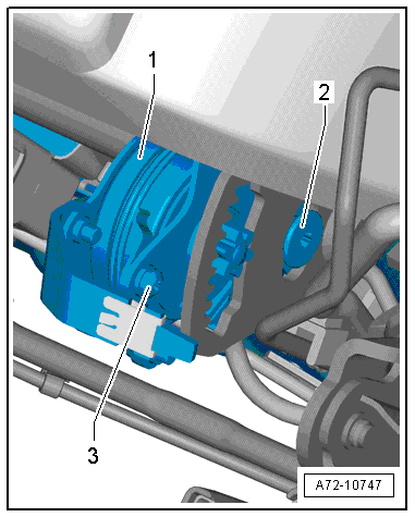
- Disconnect harness connector -3- at the seat angle adjustment motor.
- Remove the bolts -1- and the seat angle adjustment motor -4-.
Installing
Installation is performed in reverse order of removal, while noting the following:
WARNING
- Follow all Safety Precautions when working with pyrotechnic components. Refer to → Chapter "Pyrotechnic Components Safety Precautions".
- Before handling pyrotechnic components (for example, connecting the connector), the person handling it must "discharge static electricity". This can be done by touching the door striker, for example.
- Observe all measures when installing the front seat. Refer to → Chapter "Front Seat, Removing and Installing".
Installation notes, for example tightening specifications, replacing components. Refer to → Chapter "Overview - Seat Pan, Seat Angle Adjuster".
Seat Angle Adjustment Handle, Removing and Installing
Note
Removal and installation can be performed with the front seat installed.
Removing
- Remove the trim on the sill side. Refer to → Chapter "Seat Side Trim on Sill Panel Side, Removing and Installing, Front Seat (Manual)".
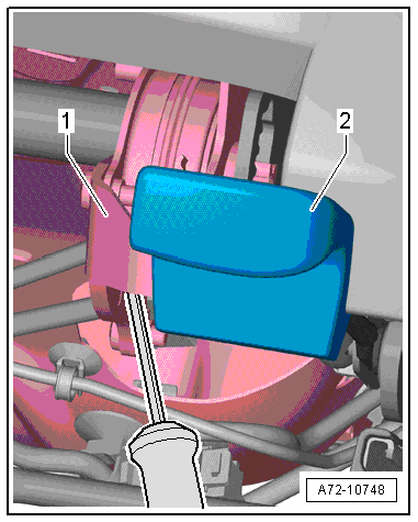
- Pry the handle -2- off the seat angle adjustment -1- by using a screwdriver to press down the clip locking spring.
Installing
Install in reverse order of removal. Note the following:
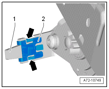
- Replace the clip on the seat angle adjuster lever. Pay attention to the installed position.
- Make sure the seat height adjustment handle engages correctly with the clip.
- The springs -arrows- (quantity: two) on the clip -2- must be on the inner side of the lever -1-.
Installation notes, for example tightening specifications, replacing components. Refer to → Chapter "Overview - Seat Pan, Seat Angle Adjuster".