Audi A6 Typ 4G: Left/Right HID Headlamp Control Module -J343-/-J344-, Removing and Installing
Left/Right HID Headlamp Control Module -J343-/-J344-, Removing and Installing, through MY 2014
 WARNING
Danger to life due to high voltage.
- For work on the yellow high voltage symbol marked areas HID headlamp must be de-energized.
- Turn off the ignition and all electrical consumers and remove the ignition key.
- Do not press the flasher.
Removing
- Turn the light switch to position "0".
- Switch off ignition and all electrical equipment. Set the ignition key outside of the vehicle.
- Do not press the flasher.
- On the right: remove the air filter housing. Refer to → 6-Cylinder TDI Common Rail 3.0L 4V Engine; Rep. Gr.23; Air Filter; Air Filter Housing, Removing and Installing or → Rep. Gr.24; Air Filter; Air Filter Housing, Removing and Installing.
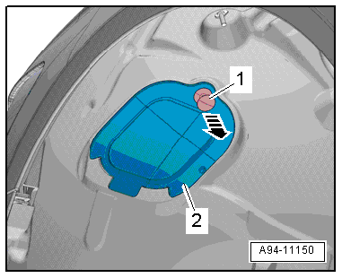
- Loosen the expanding clip -1- and disengage the cap -2- from the front wheel housing liner in direction of -arrow-.
 Note
Note
Depending on the date of manufacture, a bolt may be installed instead of the expanding clip.
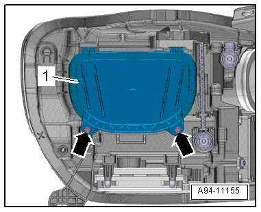
- Remove the bolts -arrows-.
- Remove the housing cover -1- by pushing the front wheel housing liner slightly to the rear.
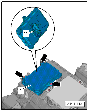
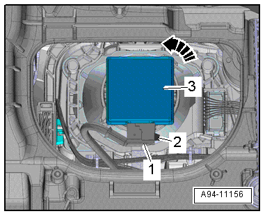
- Press the tab -1- and disconnect the connector -2-.
Note
Ignore -item 3- and -arrow-.
- Remove the front wheel spoiler. Refer to → Body Exterior; Rep. Gr.66; Wheel Housing Liner; Front Wheel Housing Liner, Removing and Installing.
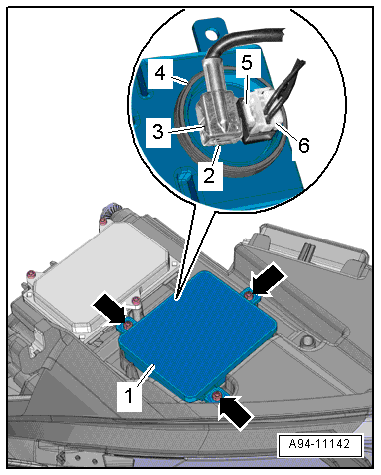
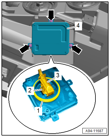
- Remove the bolts -arrows-.
- Remove the control module -1- from the headlamp housing.
- Press the tabs -2 and 5- and disconnect the adapter cable -3- and connector -6-.
- Remove the control module.
Note
If the left HID headlamp control module cannot be removed as described, then the left charge air cooling circuit cooler must be removed. Remove the left radiator for the charge air cooling circuit. Refer to → Rep. Gr.19; Radiator/Coolant Fan; Overview - Auxiliary Cooler.
Installing
Install in reverse order of removal. Note the following:
- Make sure the seal -4- between the control module and the headlamp housing is not damaged.
- Close the housing cover and tighten the bolts.
Left/Right HID Headlamp Control Module -J343-/-J344-, Removing and Installing, from MY 2015
WARNING
Risk of death due to high voltage, injury risk and environmental hazard.
HID headlamp usage and safety precautions. Refer to → Chapter "HID Headlamp Usage and Safety Precautions".
Removing
- Turn the light switch to position "0".
- Switch off ignition and all electrical equipment. Set the ignition key outside of the vehicle.
- Do not press the flasher.
- Loosen the expanding clip -1- and disengage the cap -2- from the front wheel housing liner in direction of -arrow-.
Note
Depending on the date of manufacture, a bolt may be installed instead of the expanding clip.
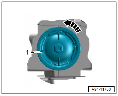
- Turn the housing cover -1- counter-clockwise in direction of -arrow- and remove it from the headlamp housing.
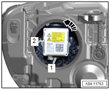
- Turn the HID bulb -2- counter-clockwise in direction of -arrow- and remove it from the housing.
- Disconnect the connector -1-.
Installing
Install in reverse order of removal. Note the following:
- Insert the new HID headlamp bulb in the housing. Do not touch the glass bulbs with bare hands.
- Installation position: the electrical connection faces down.
Left/Right Daytime Running Lamp and Position Lamp Control Module -J860-/-J861-, Removing and Installing
Left/Right Daytime Running Lamp and Position Lamp Control Module -J860-/-J861-, Removing and Installing, through MY 2014
WARNING
Danger to life due to high voltage.
- For work on the yellow high voltage symbol marked areas HID headlamp must be de-energized.
- Turn off the ignition and all electrical consumers and remove the ignition key.
- Do not press the flasher.
Removing
- Turn the light switch to position "0".
- Switch off ignition and all electrical equipment. Set the ignition key outside of the vehicle.
- Do not press the flasher.
- Remove the lock carrier cover. Refer to → Body Exterior; Rep. Gr.63; Front Bumper; Attachments, Removing and Installing.
- On the right: remove the air filter housing. Refer to → 6-Cylinder TDI Common Rail 3.0L 4V Engine; Rep. Gr.23; Air Filter; Air Filter Housing, Removing and Installing or → Rep. Gr.24; Air Filter; Air Filter Housing, Removing and Installing.
- Left: If equipped, remove the resonator with air filter. Refer to → Rep. Gr.26; Secondary Air Injection System; Secondary Air Injection Pump Motor V101, Removing and Installing.
- Remove the bolts -arrows-.
- Remove the control module -1- from the headlamp housing.
- Press the release -2- button and disconnect the connector -3-.
- Remove the control module.
Installing
Install in reverse order of removal. Note the following:
- Make sure the seal -4- between the control module and the headlamp housing is not damaged.
Left/Right Daytime Running Lamp and Position Lamp Control Module -J860-/-J861-, Removing and Installing, from MY 2015
WARNING
Danger to life due to high voltage.
- For work on the yellow high voltage symbol marked areas HID headlamp must be de-energized.
- Turn off the ignition and all electrical consumers and remove the ignition key.
- Do not press the flasher.
Removing
- Turn the light switch to position "0".
- Switch off ignition and all electrical equipment. Set the ignition key outside of the vehicle.
- Do not press the flasher.
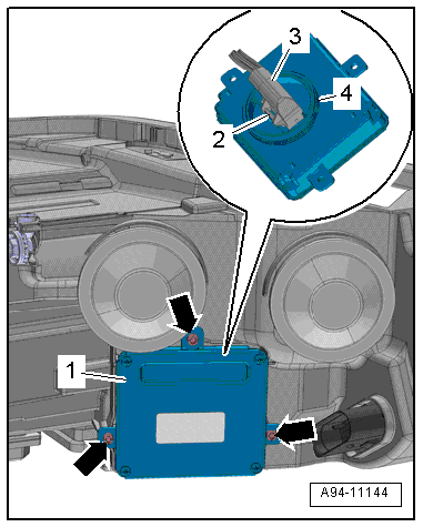
- Remove the bolts -arrows-.
- Remove the control module -4- from the headlamp housing.
- Press the release -2- button and disconnect the connector -3-.
- Remove the control module.
Installing
Install in reverse order of removal. Note the following:
- Check the seal -1- for damage.
Left/Right Headlamp Power Output Stage -J667-/-J668-, Removing and Installing
WARNING
Danger to life due to high voltage.
- For work on the yellow high voltage symbol marked areas HID headlamp must be de-energized.
- Turn off the ignition and all electrical consumers and remove the ignition key.
- Do not press the flasher.
Removing
- Turn the light switch to position "0".
- Switch off ignition and all electrical equipment. Set the ignition key outside of the vehicle.
- Do not press the flasher.
- Remove the front wheel housing liner. Refer to → Body Exterior; Rep. Gr.66; Wheel Housing Liner; Front Wheel Housing Liner, Removing and Installing.
- Remove the bolts -arrows-.
- Remove the headlamp power output stage -1-.
Installing
Install in reverse order of removal. Note the following:
- Make sure the seal -2- between the power output stage and the housing cover is not damaged.