Audi A6 Typ 4G: Multi-contour Seat Valve Block, Removing and Installing
Massage Mat Valve Block, Removing and Installing, through 08/2012
Special tools and workshop equipment required
- Hose Cutting Pliers -VAS6228-
Removing
- Remove the backrest cover. Refer to → Chapter "Backrest Cover, Removing and Installing, Multi-contour Seat".
- Disconnect the connector -3-.
- Push massage mat valve block -4- up slightly to detach it at the module carrier in direction of -arrow A-.
- Carefully release locking mechanism in direction of -arrow B-, disconnect pneumatic lines -1 and 2-.
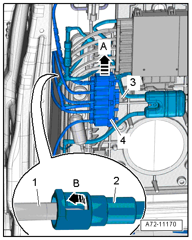
- Disconnect pneumatic lines to the massage mat air cushions at the following points (refer to → Chapter "Pneumatic Lines, Disconnecting and Connecting"):
- a - 40 mm
Installing
Install in reverse order of removal. Note the following:
Installation notes, for example tightening specifications, replacing components. Refer to → Chapter "Overview - Pneumatic System, Massage Mat".
Massage Mat Valve Block, Removing and Installing, from 09/2012
Removing
- Remove the backrest cover. Refer to → Chapter "Backrest Cover, Removing and Installing, Multi-contour Seat".
 Note
Note
If a repair is required, the pneumatic line from the compressor is not disconnected at the connection, but is disconnected by the described procedure. Refer to → Chapter "Pneumatic Lines, Disconnecting and Connecting".
Driver Side
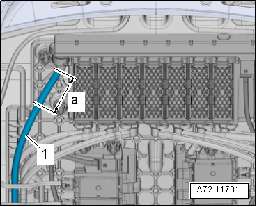
- Disconnect the pneumatic line -1- from the compressor at the following locations:
- a - 30 mm
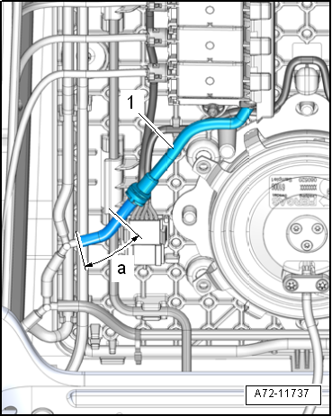
Front Passenger Side
- Disconnect the pneumatic line -1- from the compressor at the following locations:
- a - 315 mm
Continued for Both Sides
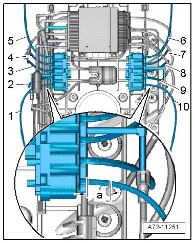
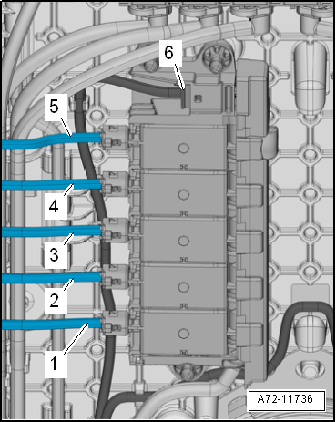
- Disconnect the connector -6-.
- Before disconnecting, mark the pneumatic line assignments to the connections at the valve block using a waterproof permanent marker.
- Disconnect the pneumatic lines -1 through 5- from all of the massage mat air cushions.
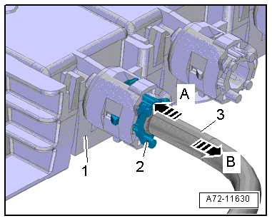
- To do this, press the release ring -2- in the direction of the valve block -1--arrow A- and at the same time pull out the pneumatic line -3- in direction of -arrow B-.
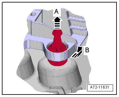
- Pull the rubber buffer lengthwise in direction of -arrow A-.
- Remove the valve block from the rubber buffer in direction of -arrow B- simultaneously.
Installing
Install in reverse order of removal. Note the following:
- Connect the pneumatic lines and give them a push again and then a final tug to see whether the coupling is locked in correctly.
Installation notes, for example tightening specifications, replacing components. Refer to → Chapter "Overview - Pneumatic System, Massage Mat".
Valve Block for Air Cushion for Lumbar Support, Seat and Backrest Bolster Adjuster Assembly, Removing and Installing, from 09/2012
Special tools and workshop equipment required
- Hose Cutting Pliers -VAS6228-
Removing
- Remove the backrest cover. Refer to → Chapter "Backrest Cover, Removing and Installing, Multi-contour Seat".
Note
If a repair is required, the pneumatic line from the compressor is not disconnected at the connection, but is disconnected by the described procedure. Refer to → Chapter "Pneumatic Lines, Disconnecting and Connecting".
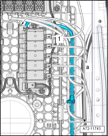
- Disconnect the pneumatic line -1- to the Valve Block 1 in Driver Seat -N475-/Valve Block 1 in Front Passenger Seat -N477- at the following position:
- a - 30 mm
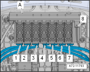
- Disconnect the connector -8-.
- Before disconnecting, mark the pneumatic line assignments to the connections at the valve block using a waterproof permanent marker.
- Disconnect the pneumatic lines -1 through 7- from the valve block -A-.
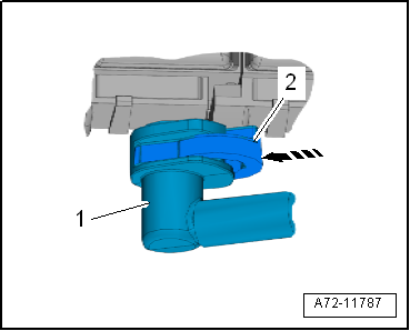
- To do this, press the release mechanism -2--arrow- and simultaneously remove the pneumatic line -1-.
- Pull the rubber buffer lengthwise -arrow A-.
- Remove the valve block from the rubber buffer -arrow B- simultaneously.
Installing
Install in reverse order of removal. Note the following:
- Connect the pneumatic line. Refer to → Chapter "Pneumatic Lines, Disconnecting and Connecting".
- Connect the pneumatic lines and give them a push again and then a final tug to see whether the coupling is locked in correctly.
Installation notes, for example tightening specifications, replacing components. Refer to → Chapter "Overview - Pneumatic System, Backrest".
