Audi A6 Typ 4G: Massage Mat, Removing and Installing
Removing
 WARNING
- Follow all Safety Precautions when working with pyrotechnic components. Refer to → Chapter "Pyrotechnic Components Safety Precautions".
- Before handling pyrotechnic components (for example, disconnecting the connector), the person handling it must "discharge static electricity". This can be done by touching the door striker, for example.
- Remove the front seat. Refer to → Chapter "Front Seat, Removing and Installing".
- Fasten the front seat on the Engine/Transmission Holder - Seat Repair Fixture -VAS6136-. Refer to → Chapter "Front Seat, Mounting on Fixture for Seat Repair".
- Remove the backrest. Refer to → Chapter "Front Backrest, Removing and Installing, Multi-contour Seat".
- Remove the backrest cover with the backrest cushion. Refer to → Chapter "Backrest Cover and Cushion, Removing and Installing, Multi-contour Seat from 09/2012".
- Separate the backrest cover and backrest cushion. Refer to → Chapter "Backrest Cover and Cushion, Separating".
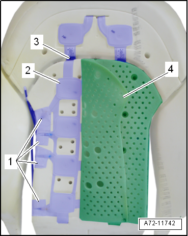
- Remove the clip -3-.
- Pull back the air guide mat -4-.
- Loosen and free up the pneumatic lines from the adhesive -1-.
- Remove the massage mat -2- from the backrest cushion.
Installing
- Route the pneumatic lines in the backrest cushion and connect them to the valve block.
- Connect the pneumatic lines and give them a push again and then a final tug to see whether the coupling is locked in correctly.
- Attach the bonding with double adhesive tape in the same location it was in when it was removed.
WARNING
- Follow all Safety Precautions when working with pyrotechnic components. Refer to → Chapter "Pyrotechnic Components Safety Precautions".
- Before handling pyrotechnic components (for example, connecting the connector), the person handling it must "discharge static electricity". This can be done by touching the door striker, for example.
Install in reverse order of removal.
Installation notes, for example tightening specifications, replacing components. Refer to → Chapter "Overview - Pneumatic System, Massage Mat".
Driver Side Massage Function Button -E670-/Front Passenger Massage Function Button -E671-, Removing and Installing
Removing
- Remove the trim on the sill side. Refer to → Chapter "Seat Side Trim on Sill Panel Side/Front Seat Trim, Removing and Installing, Multi-contour Seat".
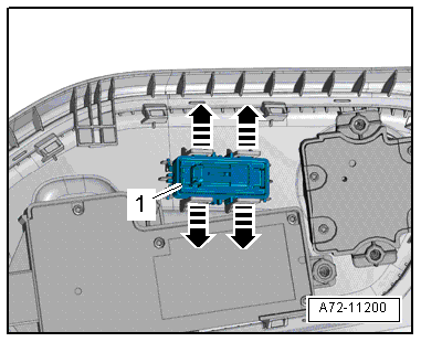
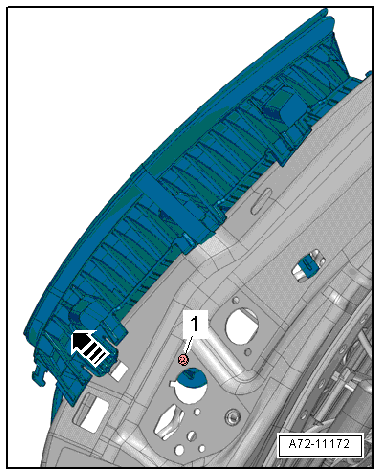
- Press out massage function button -1- from the trim and remove it by releasing the locks -arrows-.
Installing
Install in reverse order of removal. Note the following:
- Insert massage function button and press on it until it audibly engages.
Seat Bolster Adjuster, Removing and Installing
Removing
WARNING
- Follow all Safety Precautions when working with pyrotechnic components. Refer to → Chapter "Pyrotechnic Components Safety Precautions".
- Before handling pyrotechnic components (for example, disconnecting the connector), the person handling it must "discharge static electricity". This can be done by touching the door striker, for example.
- Remove the front seat. Refer to → Chapter "Front Seat, Removing and Installing".
- Remove the backrest. Refer to → Chapter "Front Backrest, Removing and Installing, Multi-contour Seat".
- Remove seat cover with seat cushion. Refer to → Chapter "Seat Pan Cover and Cushion, Removing and Installing, Multi-contour Seat".
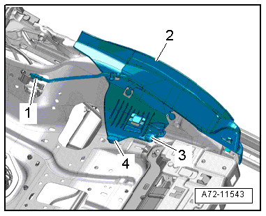
- Remove the expanding rivets -3 and 4-.
- Free up the pneumatic line -1-, disengage the seat adjustment -2- from the lower seat frame and remove it.
Installing
WARNING
- Follow all Safety Precautions when working with pyrotechnic components. Refer to → Chapter "Pyrotechnic Components Safety Precautions".
- Before handling pyrotechnic components (for example, connecting the connector), the person handling it must "discharge static electricity". This can be done by touching the door striker, for example.
- Observe all measures when installing the front seat. Refer to → Chapter "Front Seat, Removing and Installing".
Install in reverse order of removal. Note the following:
Installation notes, for example tightening specifications, replacing components. Refer to → Chapter "Overview - Pneumatic System, Seat-/Backrest Bolster Adjuster".
Backrest Bolster Adjuster, Removing and Installing
Backrest Bolster Inflation Adjuster, Removing and Installing, through 08/2012
Removing
- Remove the backrest cover with the backrest cushion. Refer to → Chapter "Backrest Cover and Cushion, Removing and Installing, Multi-contour Seat through 08/2012".
- Remove bolt -1-, release lock -arrow-.
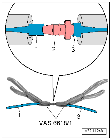
- Disconnect the pneumatic lines -1 and 3- at the line connector -2-.
Installing
Install in reverse order of removal. Note the following:
Installation notes, for example tightening specifications, replacing components. Refer to → Chapter "Overview - Pneumatic System, Seat-/Backrest Bolster Adjuster".
Backrest Bolster Inflation Adjuster, Removing and Installing, from 09/2012
Removing
- Remove the backrest cover with the backrest cushion. Refer to → Chapter "Backrest Cover and Cushion, Removing and Installing, Multi-contour Seat from 09/2012".
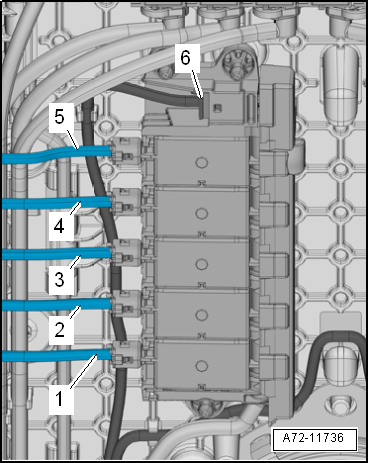
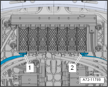
- Before disconnecting, mark the pneumatic line assignments to the connections at the valve block using a waterproof permanent marker.
- Disconnect the pneumatic lines -1 and 2- to the backrest bolster adjuster air cushions.
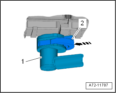
- To do this, press the release mechanism -2--arrow- and simultaneously remove the pneumatic line -1-.
- Free up the pneumatic lines from the backrest bolster adjuster air cushions.
- Remove bolt -1-, release lock -arrow-.
Installing
Install in reverse order of removal. Note the following:
Installation notes, for example tightening specifications, replacing components. Refer to → Chapter "Overview - Pneumatic System, Seat-/Backrest Bolster Adjuster".
