Audi A6 Typ 4G: Overview - Telephone
Cell Phone Preparation, 9ZF, through MY 2014
The Telephone Baseplate -R126- is installed in the center console. The telephone is operated either by the Infotainment system MMI or by the Cellular Telephone -R54-.
The microphones for the Microphone Unit In Front Roof Module -R164- are integrated in the Front Interior Lamp -W1-. On microphone (Left Front Microphone -R140-) is connected directly to the Information Electronics Control Module 1 -J794-.
The connection for the antenna is located on the Telephone Baseplate -R126-.
9ZF - Cell phone preparation in the Information Electronics Control Module 1 -J794-
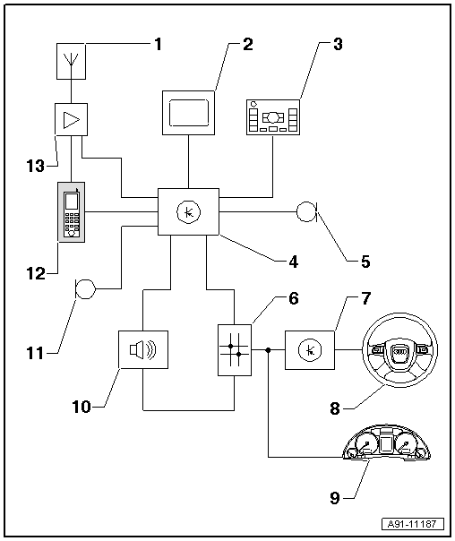
1 - Roof Antenna -R216-
2 - Front Information Display Control Head -J685-, display in center of the instrument panel
3 - Multimedia System Control Head -E380- in the center console
4 - Information Electronics Control Module 1 -J794- inside the instrument panel
5 - Right Front Microphone -R141-, Microphone Unit in Front Roof Module -R164- in the Front Interior Lamp -W1-
6 - Data Bus On Board Diagnostic Interface -J533- under the rear bench seat
7 - Steering Column Electronics Control Module -J527- on steering column at steering column switch
8 - Multifunction Steering Wheel
9 - Instrument Cluster Control Module -J285- in the instrument panel
10 - Digital Sound System Control Module -J525- in luggage compartment on left rear side
11 - Left Front Microphone -R140-, Microphone Unit in Front Roof Module -R164- in the Front Interior Lamp -W1-
12 - Telephone Baseplate - R126- with Cellular Telephone -R54-
13 - Cellular Telephone Amplifier -R86- in luggage compartment on right rear side
Fault finding is performed via "Guided Fault Finding" on the Vehicle Diagnostic Tester.
Antenna wires, repairing. Refer to → Electrical Equipment; Rep. Gr.97; Antenna Wires, Repairing.
Notes on Bluetooth technology
A standardized radio connection system is used to transmit data between the Information Electronics Control Module 1 -J794- and Telephone Handset -R37-/Cellular Telephone -R54- - Bluetooth Technology.
The range of the radio connection is approximately 10 m.
Notes on MOST Bus
The optical Data bus "MOST Bus" is used in addition to the CAN Bus.
A fiber-optic cable is used. Fiber optic cables are routed inside corrugated tubes for protection.
Replace complete fiber-optic cable if possible.
The front surface of the connectors must not be dirty.
If disconnecting the connectors: Attach Fiber-Optic Repair Set - Connector Protective Caps -VAS6223/9-.
When installing fiber-optic cables, make sure not to go below the minimum bending radius of 25 mm. Do not crush or kink fiber-optic cables.
Repairing fiber-optic cables. Refer to → Electrical Equipment General Information; Rep. Gr.97; Wiring Harness and Connector Repairs; Fiber-Optic Cables, Repairing.
Bluetooth Car Phone, 9ZW, through MY 2014
The Bluetooth car phone also supports the operation of Bluetooth Cellular Telephone -R54-. The Bluetooth Cellular Telephone -R54- does not have to be mounted in a bracket or be linked to the vehicle hands-free calling.
The Bluetooth link is the only means of connecting the cell phone. The Cellular Telephone -R54- SIM card (directory) can also be read out.
The Bluetooth vehicle telephone has its own Telephone Handset -R37- with a SIM card slot and charging base.
The Telephone Handset -R37-, the hands-free calling with the multifunction steering wheel and the voice recognition system can be used to operate the Bluetooth car phone and the Cellular Telephone -R54-.
The Bluetooth Antenna -R152- is integrated in the Information Electronics Control Module 1 -J794-.
The microphones for the Microphone Unit In Front Roof Module -R164- are integrated in the Front Interior Lamp -W1-. On microphone (Left Front Microphone -R140-) is connected directly to the Information Electronics Control Module 1 -J794-.
The connection for the antenna is located on the Information Electronics Control Module 1 -J794-.
9ZW - Bluetooth car phone in the Information Electronics Control Module 1 -J794-
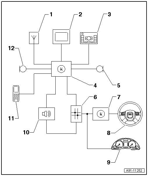
1 - Roof Antenna -R216-
2 - Front Information Display Control Head -J685-, display in center of the instrument panel
3 - Multimedia System Control Head -E380- in the center console
4 - Information Electronics Control Module 1 -J794- inside the instrument panel
5 - Right Front Microphone -R141-, Microphone Unit in Front Roof Module -R164- in the Front Interior Lamp -W1-
6 - Data Bus On Board Diagnostic Interface -J533- under the rear bench seat
7 - Steering Column Electronics Control Module -J527- on steering column at steering column switch
8 - Multifunction Steering Wheel
9 - Instrument Cluster Control Module -J285- in the instrument panel
10 - Digital Sound System Control Module -J525- in luggage compartment on left rear side
11 - Telephone Baseplate -R126- with Telephone Handset -R37-
12 - Left Front Microphone -R140-, Microphone Unit in Front Roof Module -R164- in the Front Interior Lamp -W1-
Fault finding is performed via "Guided Fault Finding" on the Vehicle Diagnostic Tester.
Antenna wires, repairing. Refer to → Electrical Equipment; Rep. Gr.97; Antenna Wires, Repairing.
Notes on Bluetooth technology
A standardized radio connection system is used to transmit data between the Information Electronics Control Module 1 -J794- and Telephone Handset -R37-/Cellular Telephone -R54- - Bluetooth Technology.
The range of the radio connection is approximately 10 m.
Notes on MOST Bus
The optical Data bus "MOST Bus" is used in addition to the CAN Bus.
A fiber-optic cable is used. Fiber optic cables are routed inside corrugated tubes for protection.
Replace complete fiber-optic cable if possible.
The front surface of the connectors must not be dirty.
If disconnecting the connectors: Attach Fiber-Optic Repair Set - Connector Protective Caps -VAS6223/9-.
When installing fiber-optic cables, make sure not to go below the minimum bending radius of 25 mm. Do not crush or kink fiber-optic cables.
Repairing fiber-optic cables. Refer to → Electrical Equipment General Information; Rep. Gr.97; Wiring Harness and Connector Repairs; Fiber-Optic Cables, Repairing.
Bluetooth Hands-Free Calling, 9ZX
The Information Electronics Control Module 1 -J794- is installed with the Microphone Unit In Front Roof Module -R164- and is part of the hands-free setup. Bluetooth is connected via the Cellular Telephone -R54-.
The Bluetooth Antenna -R152- is integrated in the Information Electronics Control Module 1 -J794-.
9ZX - Bluetooth hands-free calling in the Information Electronics Control Module 1 -J794-
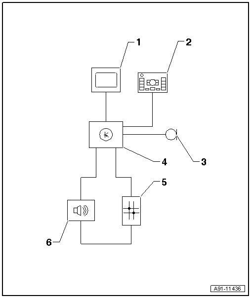
1 - Front Information Display Control Head -J685-, display in center of the instrument panel
2 - Multimedia System Control Head -E380- in the Center Console
3 - Right Front Microphone -R141-, Microphone Unit in Front Roof Module -R164- in the Front Interior Lamp -W1-
4 - Information Electronics Control Module 1 -J794- inside the instrument panel
5 - Data Bus On Board Diagnostic Interface -J533- under the rear bench seat
6 - Digital Sound System Control Module -J525- in luggage compartment on left rear side
Antennas with Bluetooth hands-free calling, 9ZX
- No Telephone Antenna -R65- is installed
- No LTE antennas (-R297-/-R306-) are installed
1 - Information Electronics Control Module 1 -J794-
2 - Not Installed
3 - Roof Antenna -R216-
4 - Not Installed
5 - Not Installed
6 - Not Installed
Fault finding is performed via "Guided Fault Finding" on the Vehicle Diagnostic Tester.
Antenna wires, repairing. Refer to → Electrical Equipment; Rep. Gr.97; Antenna Wires, Repairing.
Notes on Bluetooth technology
A standardized radio connection system is used to transmit data between the Information Electronics Control Module 1 -J794- and Telephone Handset -R37-/Cellular Telephone -R54- - Bluetooth Technology.
The range of the radio connection is approximately 10 m.
Notes on MOST bus
The optical data bus "MOST Bus" is used in addition to the CAN Bus.
A fiber-optic cable is used. Fiber optic cables are routed inside corrugated tubes for protection.
Replace the complete fiber-optic cable if possible.
The front surface of the connectors must not be contaminated.
If disconnecting the connectors: Attach the Fiber-Optic Repair Set - Connector Protective Caps -VAS 6223/9-.
When routing fiber-optic cables, make sure not to go below the minimum bending radius of 25 mm. Do not crush or kink the fiber-optic cables.
Repairing fiber-optic cables. Refer to → Electrical Equipment General Information; Rep. Gr.97; Wiring Harness and Connector Repairs; Fiber-Optic Cables, Repairing.
Telephone, Audi Phone Box and Audi Connect, 9ZC from MY 2015
The Telephone Baseplate -R126- (phone box) is installed in the center console. The telephone is operated either by the Infotainment system MMI or by the Cellular Telephone -R54-.
The microphones for the Microphone Unit In Front Roof Module -R164- are integrated in the Front Interior Lamp -W1-. One microphone (Left Front Microphone -R140-) is connected directly to the Information Electronics Control Module 1 -J794-.
The connection to the cellular network takes place via the Telephone Antenna -R65-.
The antenna connection is located on the Cellular Telephone Amplifier -R86-.
For the data transfer two LTE antennas are installed (LTE Antenna 1 -R297-/LTE Antenna 2 - R306-) and connected with the Information Electronics Control Module 1 -J794-.
9ZC - Audi connect and Audi phone box
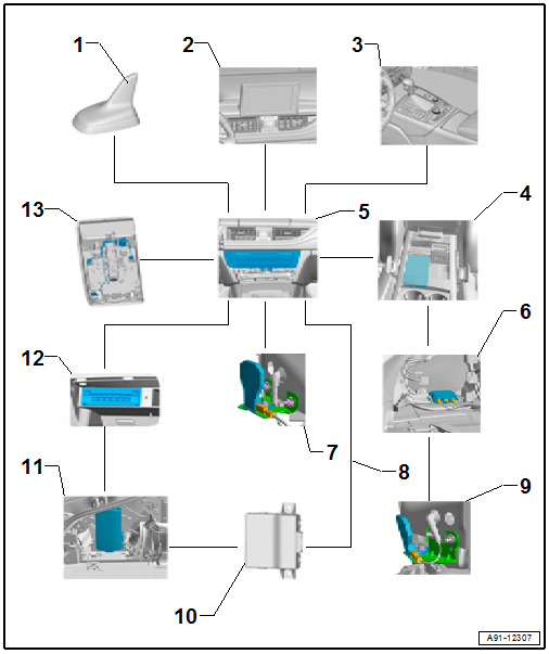
1 - Telephone Antenna -R65- in the Roof Antenna -R216-
- only on ER3
- LTE Antenna 2 -R306- in the Roof Antenna -R216-
- only on ER1/ER2
2 - Front Information Display Control Head -J685-, display in center of the instrument panel
3 - Multimedia System Control Head -E380- in the center console
4 - Telephone Baseplate - R126- with Cellular Telephone -R54-
5 - Information Electronics Control Module 1 -J794- inside the instrument panel
6 - Cellular Telephone Amplifier -R86- in luggage compartment on left rear side
7 - LTE Antenna 1 -R297- under the rear bumper cover on the right side
8 - MOST Bus
9 - Telephone Antenna -R65-, under the rear bumper cover on the right side
- only on ER1/ER2
- LTE Antenna 2 -R306- under the rear bumper cover on the right side
- only on ER3
10 - Data Bus On Board Diagnostic Interface -J533- under the rear bench seat
11 - Digital Sound System Control Module -J525- in luggage compartment on left rear side
12 - DVD Changer -R161- in the glove compartment
13 - Right Front Microphone -R141-, Microphone Unit in Front Roof Module -R164- in the Front Interior Lamp -W1-
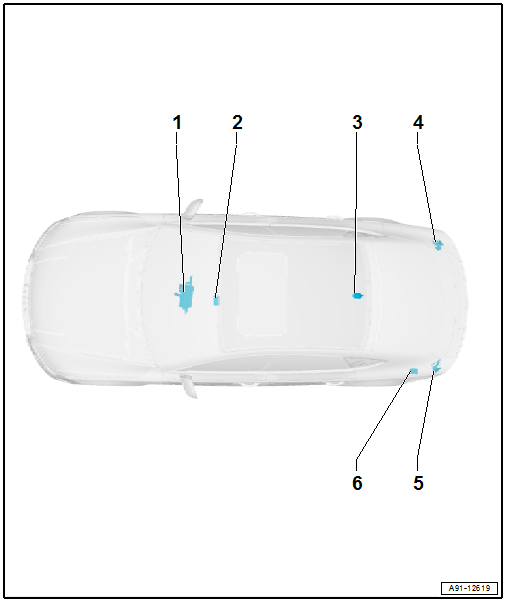
Antennas on Audi phone box and Audi connect, 9ZC
- Europe and Rest of World (ER1/ER2): the Telephone Antenna -R65- is installed under the rear bumper cover on the left side
- USA (ER3): the Telephone Antenna -R65- is installed in the Roof Antenna -R216-
- The LTE Antenna 1 -R297- is installed under the rear bumper cover on the right side
- Europe and Rest of World (ER1/ER2): the LTE Antenna 2 -R306- is installed in the Roof Antenna -R216-
- USA (ER3): the LTE Antenna 2 -R306- is installed under the rear bumper cover on the left side
1 - Information Electronics Control Module 1 -J794-
2 - Telephone Baseplate -R126-
3 - Roof Antenna -R216-
- Telephone Antenna -R65-, ER3
- LTE Antenna 2 -R306-, ER1/ER2
4 - Right Bumper Antenna
- LTE Antenna 1 -R297-, ER1/ER2/ER3
5 - Left Bumper Antenna
- Telephone Antenna -R65-, ER1/ER2
- LTE Antenna 2 -R306-, ER3
6 - Cellular Telephone Amplifier -R86-
Fault finding is performed via "Guided Fault Finding" on the Vehicle Diagnostic Tester.
Antenna wires, repairing. Refer to → Electrical Equipment; Rep. Gr.97; Antenna Wires, Repairing.
Notes on Bluetooth technology
A standardized radio connection is used for data transfer between the Information Electronics Control Module 1 -J794- and Cellular Telephone -R54- - Bluetooth Technology.
The range of the radio connection is approximately 10 m.
Telephone, Audi Phone Box, 9ZE from MY 2015
The Telephone Baseplate -R126- (phone box) is installed in the center console. The telephone is operated either by the Infotainment system MMI or by the Cellular Telephone -R54-.
The microphones for the Microphone Unit In Front Roof Module -R164- are integrated in the Front Interior Lamp -W1-. On microphone (Left Front Microphone -R140-) is connected directly to the Information Electronics Control Module 1 -J794-.
The Telephone Antenna -R65- in the Roof Antenna -R216- connects to the cellular network.
The antenna connection is located on the Cellular Telephone Amplifier -R86-.
9ZE - Audi phone box
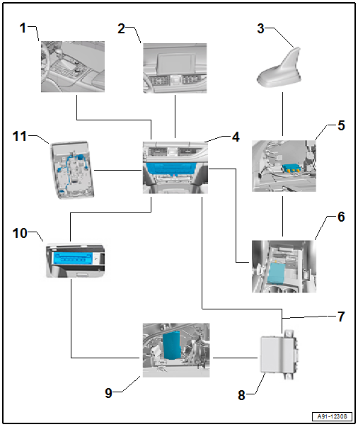
1 - Multimedia System Control Head -E380- in the center console
2 - Front Information Display Control Head -J685-, display in center of the instrument panel
3 - Telephone Antenna -R65- in the Roof Antenna -R216-
4 - Information Electronics Control Module 1 -J794- inside the instrument panel
5 - Cellular Telephone Amplifier -R86- in luggage compartment on left rear side
6 - Telephone Baseplate - R126- with Cellular Telephone -R54-
7 - MOST Bus
8 - Data Bus On Board Diagnostic Interface -J533- under the rear bench seat
9 - Digital Sound System Control Module -J525- in luggage compartment on left rear side
10 - DVD Changer -R161- in the glove compartment
11 - Right Front Microphone -R141-, Microphone Unit in Front Roof Module -R164- in the Front Interior Lamp -W1-
Antennas on Audi phone box, 9ZE
- The Telephone Antenna -R65- is installed in the Roof Antenna -R216-
- No LTE antennas (-R297-/-R306-) are installed
1 - Information Electronics Control Module 1 -J794-
2 - Telephone Baseplate -R126-
3 - Roof Antenna -R216-
- Telephone Antenna -R65-
4 - Not Installed
5 - Not Installed
6 - Cellular Telephone Amplifier -R86-
Fault finding is performed via "Guided Fault Finding" on the Vehicle Diagnostic Tester.
Antenna wires, repairing. Refer to → Electrical Equipment; Rep. Gr.97; Antenna Wires, Repairing.
Notes on Bluetooth technology
A standardized radio connection is used for data transfer between the Information Electronics Control Module 1 -J794- and Cellular Telephone -R54- - Bluetooth Technology.
The range of the radio connection is approximately 10 m.
Telephone, Audi Connect with Bluetooth Car Phone, 9ZK, from MY 2015
The Information Electronics Control Module 1 -J794- is installed with the Microphone Unit In Front Roof Module -R164- and is part of the car phone. Bluetooth is connected via the Cellular Telephone -R54-.
The Cellular Telephone -R54- antenna connects to the cellular network.
The Bluetooth Antenna -R152- is integrated in the Information Electronics Control Module 1 -J794-.
For the data transfer two LTE antennas are installed (LTE Antenna 1 -R297-/LTE Antenna 2 - R306-) and connected with the Information Electronics Control Module 1 -J794-.
9ZK - Audi connect with Bluetooth car phone
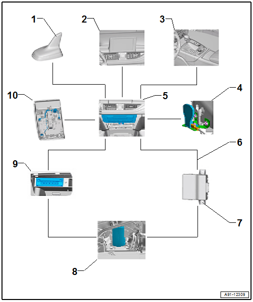
1 - Telephone Antenna -R65- in the Roof Antenna -R216-
- only on ER5 (through 11/08/2015), ER6 (through MY 2017)
- LTE Antenna 2 -R306- in the Roof Antenna -R216-
- only on ER1/ER2, ER5 (from 11/08/2015), ER6 (from MY 2017)
2 - Front Information Display Control Head -J685- in center of the instrument panel
3 - Multimedia System Control Head -E380- in the center console
4 - LTE Antenna 1 -R297- under the left rear bumper cover
- only on ER1/ER2, ER5 (from 11/08/2015), ER6 (from MY 2017)
- LTE Antenna 1 -R297- under the rear bumper cover on the right side
- only on ER3
- LTE Antenna 2 -R306- under the rear bumper cover on the left side
- only on ER3
5 - Information Electronics Control Module 1 -J794- inside the instrument panel
6 - MOST Bus
7 - Data Bus On Board Diagnostic Interface -J533- under the rear bench seat
8 - Digital Sound System Control Module -J525- in luggage compartment on left rear side
9 - DVD Changer -R161- in the glove compartment
10 - Microphone Unit in Front Roof Module -R164-, Left Front Microphone -R140- in the Front Interior Lamp -W1-
Antennas for Audi connect with Bluetooth car phone, 9ZK
- Europe and Rest of World (ER1/ER2), USA (ER3): There is no Telephone Antenna -R65-
- Japan (ER5) through 11/08/2015, China (ER6) through MY 2017: the Telephone Antenna -R65- is installed in the Roof Antenna -R216-
- Europe and Rest of World (ER1/ER2), Japan (ER5) from 11/08/2015, China (ER6) from MY 2017: LTE Antenna 1 and 2 (-R297-/-R306-) are installed, LTE Antenna 2 -R306- is in the Roof Antenna -R216- and LTE Antenna 1 -R297- is under the rear bumper cover on the left side
- USA (ER3): There are LTE antennas (LTE Antenna 1 and 2 -R297-/-R306-) installed, LTE Antenna 1 -R297- is under the rear bumper cover on the right side and LTE Antenna 2 -R306- is under the rear bumper cover on the left side
1 - Information Electronics Control Module 1 -J794-
2 - Not Installed
3 - Roof Antenna -R216-
- Telephone Antenna -R65-, only on ER5 (through 11/08/2015), ER6 (through MY 2017)
- LTE Antenna 2 -R306-, only on ER1/ER2, ER5 (from 11/08/2015), ER6 (from MY 2017)
4 - Right Bumper Antenna
- LTE Antenna 1 -R297-, only on ER3
5 - Left Bumper Antenna
- LTE Antenna 1 -R297-, only on ER1/ER2, ER5 (from 11/08/2015), ER6 (from MY 2017)
- LTE Antenna 2 -R306-, ER3
6 - Not Installed
Fault finding is performed via "Guided Fault Finding" on the Vehicle Diagnostic Tester.
Antenna wires, repairing. Refer to → Electrical Equipment; Rep. Gr.97; Antenna Wires, Repairing.
Notes on Bluetooth technology
A standardized radio connection is used for data transfer between the Information Electronics Control Module 1 -J794- and Cellular Telephone -R54- - Bluetooth Technology.
The range of the radio connection is approximately 10 m.
