Audi A6 Typ 4G: Parking Brake
Overview - Parking Brake
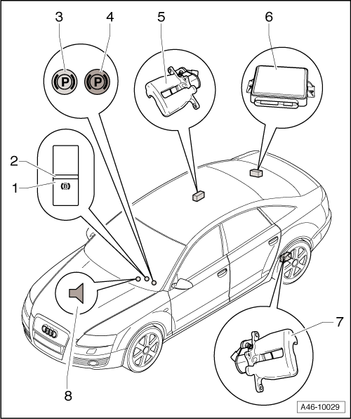
1 - Electromechanical Parking Brake Button -E538-
- Removing and installing. Refer to → Electrical Equipment; Rep. Gr.96; Controls; Electromechanical Parking Brake ButtonE538/-AUTO HOLD- ButtonE540, Removing and Installing.
2 - LED Display, Parking Brake Set
3 - Electromechanical Parking Brake Indicator Lamp (Yellow)
4 - Electromechanical Parking Brake System Function Lamp
5 - Right Parking Brake Motor -V283- for Electromechanical Parking Brake
- 12 Nm.
- Removing and installing. Refer to → Chapter "Left/Right Parking Brake Motor -V282-/-V283-, Removing and Installing".
6 - Electromechanical Parking Brake Control Module -J540-
- Component location. Refer to → Fig. "Component Location Electromechanical Parking Brake Control Module -J540-, Tightening Specification".
- Removing and installing. Refer to → Chapter "Electromechanical Parking Brake Control Module -J540-, Removing and Installing".
7 - Left Parking Brake Motor -V282- for Electromechanical Parking Brake
- 12 Nm.
- Removing and installing. Refer to → Chapter "Left/Right Parking Brake Motor -V282-/-V283-, Removing and Installing".
8 - Acoustic Signal
- Warning when operating while driving
- Warning when malfunction in system is detected
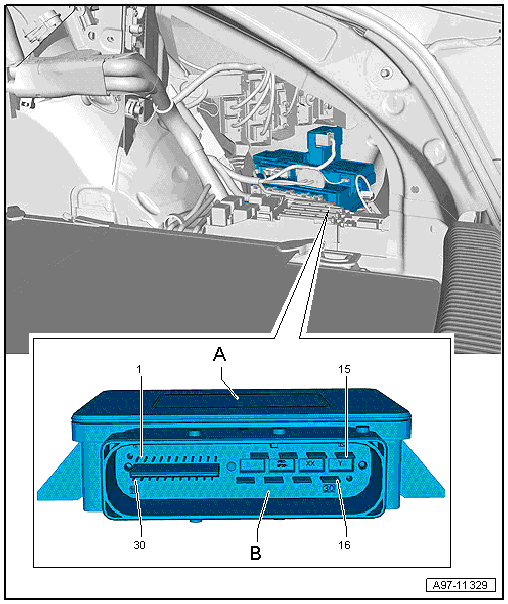
Component Location Electromechanical Parking Brake Control Module -J540-, Tightening Specification
- Component location: behind the right luggage compartment side trim panel.
- Threaded version: tighten the nuts to 3 Nm.
Electromechanical Parking Brake Control Module -J540-, Removing and Installing
Special tools and workshop equipment required
- Torque Wrench 1410 -VAG1410-
 Note
Note
If the Electromechanical Parking Brake Control Module -J540- is being replaced, select the "Replace" function for the Electromechanical Parking Brake Control Module -J540- on the Vehicle Diagnostic Tester in Guided Functions.
Component location. Refer to → Fig. "Component Location Electromechanical Parking Brake Control Module -J540-, Tightening Specification".
Removing
- Remove the Fuse Panel F -SF-. Refer to → Electrical Equipment; Rep. Gr.97; Relay Panel, Fuse Panels and E-Boxes; Relay Panel and Fuse Panel in Luggage Compartment Right, Removing and Installing.
- If equipped, remove the lower frame for the control modules. Refer to → Electrical Equipment; Rep. Gr.97; Control Modules.
- Vehicles without lower frame for the control modules: remove the nuts.
- Vehicles with lower frame for the control modules: remove the Electromechanical Parking Brake Control Module -J540- from the threaded pins.
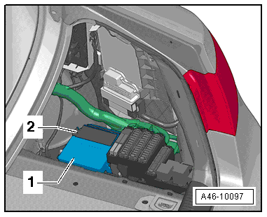
- Slide the locking mechanism for the connection -2- forward.
- Remove the Electromechanical Parking Brake Control Module -J540--1- with the connector.
- Disconnect the connector and remove the control module.
Installing
- Connect the connector -2- to the Electromechanical Parking Brake Control Module -J540-.
- Slide the retainer on the connector back and lock it.
- Insert the control module.
- If equipped, install the lower frame for the control module. Refer to → Electrical Equipment; Rep. Gr.97; Relay Panel, Fuse Panels, E-Boxes; Relay Panel, Fuse Panel and E-Box Component Location Overview.
- Install the Fuse Panel F -SF-. Refer to → Electrical Equipment; Rep. Gr.97; Relay Panel, Fuse Panels and E-Boxes; Relay Panel and Fuse Panel in Luggage Compartment Right, Removing and Installing.
- If the Electromechanical Parking Brake Control Module -J540- is being replaced, select the "Replace" function for the Electromechanical Parking Brake Control Module -J540- on the Vehicle Diagnostic Tester in Guided Functions.
Left/Right Parking Brake Motor -V282-/-V283-, Removing and Installing
Special tools and workshop equipment required
- Vehicle Diagnostic Tester
- Torque Wrench 1331 5-50Nm -VAG1331-
Removing
- Loosen the parking brake.
- Switch off the ignition.
Note
Ignition must be switched off for at least 30 seconds before disconnecting the connector.
- Remove the affected rear wheel, while observing the safety precautions for vehicles with ceramic brakes. Refer to → Suspension, Wheels and Steering; Rep. Gr.44; Wheels, Tires.
Note
Clean the entire area around the connector and parking brake motor/brake caliper.
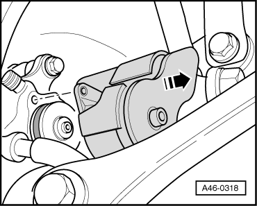
- Disconnect the connector -arrow- to the parking brake motor.
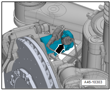
- Remove both parking brake motor bolts.
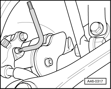
- Remove the parking brake motor -arrow-.
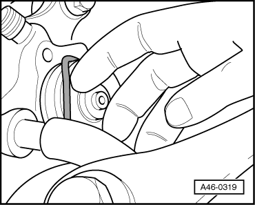
- Remove sealing ring with a suitable tool.
Note
- Be careful not to damage the ring groove on the seal and the contact surface on the parking brake motor.
- Do not use any tools with sharp edges.
- Clean ring groove and contact surfaces if dirty. Only use brake cleaner.
Installing
- Install the new seal.
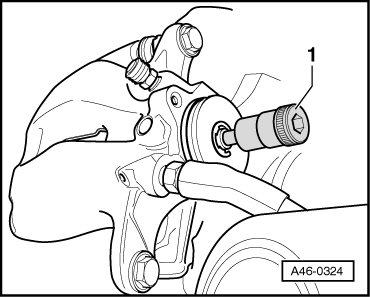
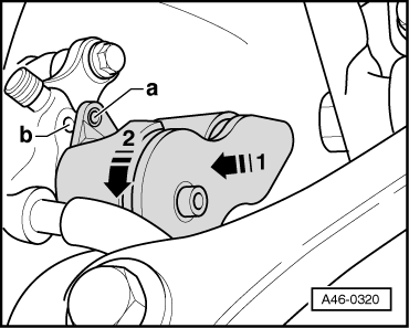
- If required, move the adjusting screw in the brake caliper back a little using a socket -1- to make it easier to install the parking brake motor.
- Position the parking brake motor -arrow 1-.
Note
Make sure that the seal is seated correctly
- Turn the parking brake motor -arrow 2- so that the hole for the bolt -a- and the thread in the brake caliper housing -b- are covered.
Note
Make sure that the parking brake motor is seated flush against the brake caliper housing.
 Caution
There is a risk of damaging the threads.
- Position the bolts by hand and screw in a few turns.
- If the thread is damaged, the entire brake caliper must be replaced.
- Tighten the parking brake motor bolts.
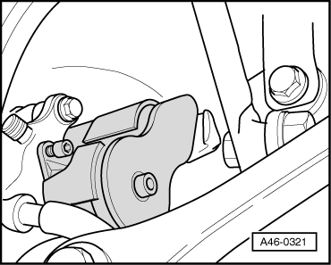
- Connect the connector -arrow- to the parking brake motor.
- Install the rear wheel. Refer to → Suspension, Wheels, Steering; Rep. Gr.44; Wheels, Tires.
- Switch the ignition on.
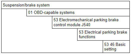
- After entering the VIN, select Guided Functions.
- Perform a basic setting.
- Continue to follow the instructions in the vehicle diagnostic tester display.
