Audi A6 Typ 4G: Brake Pedal
Overview - Brake Pedal
 WARNING
Risk of accident!
The path of the brake pedal must not be shortened by extra floor mats.
 Note
Note
Lubricate all bearing and contact surfaces with Grease -G 000 450 02-.
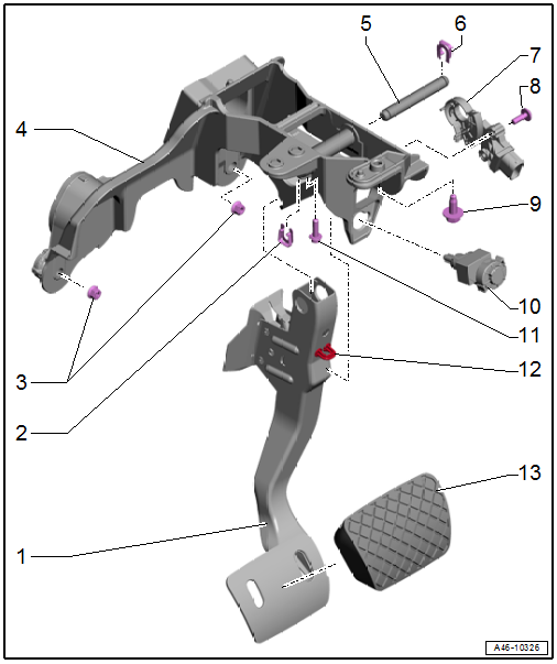
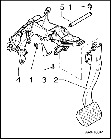
1 - Brake Pedal
- Disconnecting from brake booster. Refer to → Chapter "Brake Pedal, Disconnecting from Brake Booster".
- Connect with brake booster. Refer to → Chapter "Brake Pedal, Attaching to Brake Booster".
- Removing and installing. Refer to → Chapter "Brake Pedal, Removing and Installing".
 Caution
If possible, leave the brake pedal stop installed; it could break the mount for the Brake Lamp Switch -F- if the brake pedal is released too quickly.
2 - Clamp
- Replace after removing
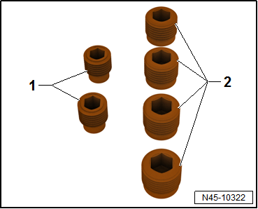
3 - Nuts
- 8 Nm
4 - Mounting Bracket for Pedal Assembly
- Removing and installing. Refer to → Chapter "Mounting Bracket, Removing and Installing".
5 - Mounting Pin
- For brake pedal
6 - Clamp
- Replace after removing
7 - Brake Pedal Position Sensor -G100-
- With magnet holder
- For vehicles with a high-voltage system
- Removing and installing. Refer to → Chapter "Brake Pedal Position Sensor, Removing and Installing".
8 - Bolt
- 4.5 Nm
9 - Bolt
- 8 Nm
- Holds the mounting pin in place
10 - Brake Lamp Switch -F-
- Removing and installing. Refer to → Chapter "Brake Lamp Switch, Removing and Installing".
11 - Bolt
- 20 Nm
- Pedal bracket to steering column
12 - Stop
Caution
If possible, leave the brake pedal stop installed; it could break the mount for the Brake Lamp Switch -F- if the brake pedal is released too quickly.
13 - Pedal Rubber
Mounting Bracket, Removing and Installing
Special tools and workshop equipment required
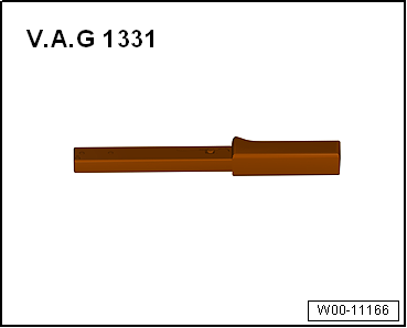
- Torque Wrench 1331 5-50Nm -VAG1331-
Removing
- Remove the tower brace. Refer to → Suspension, Wheels, Steering; Rep. Gr.40; Suspension Strut, Upper Control Arm; Tower Brace, Removing and Installing.
- Remove the footwell vent. Refer to → Heating, Ventilation and Air Conditioning; Rep. Gr.87; Air Guide; Driver Side Footwell Vent, Removing and Installing.
- Disconnect the brake pedal from the brake booster. Refer to → Chapter "Brake Pedal, Disconnecting from Brake Booster".
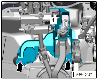
- Press the connector retainer -1- upward -arrow- and disconnect the connector -2-.
- Free up the wire.
Note
Ignore -item 3-.
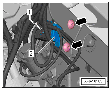
Vehicles with high-voltage system:
- Disconnect the connector -1- on the Brake Pedal Position Sensor -G100--item 2-.
Note
Ignore the -arrows-.
Continuation for All Vehicles:
- Remove the nuts -arrows- and bolt -1-, then remove the mounting bracket with the brake pedal and accelerator pedal module installed.
- Remove the brake pedal. Refer to → Chapter "Brake Pedal, Removing and Installing".
- Remove the accelerator pedal module. Refer to → Fuel Supply System; Rep. Gr.20; Accelerator Mechanism; Accelerator Pedal Module with Accelerator Pedal Position Sensor G79/G185, Removing and Installing
Installing
Install in reverse order of removal and note the following:
- Install the accelerator pedal module. Refer to → Fuel Supply System; Rep. Gr.20; Accelerator Mechanism; Accelerator Pedal Module with Accelerator Pedal Position Sensor G79/G185, Removing and Installing
- Install the brake pedal. Refer to → Chapter "Brake Pedal, Removing and Installing".
- Install the pedal bracket, with the brake pedal installed, and the accelerator pedal module.
- The pedal bracket must fit into the guides in the bulkhead.
- Install and tighten the brake booster/mounting bracket bolts -arrows-.
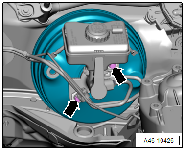
- Tighten the nuts -arrows- and the bolt -1-.
- Install the footwell vent. Refer to → Heating, Ventilation and Air Conditioning; Rep. Gr.87; Air Guide; Driver Side Footwell Vent, Removing and Installing.
- Attach the brake pedal to the brake booster. Refer to → Chapter "Brake Pedal, Attaching to Brake Booster".
- Install the tower brace. Refer to → Suspension, Wheels, Steering; Rep. Gr.40; Suspension Strut, Upper Control Arm; Tower Brace, Removing and Installing.
WARNING
Risk of accident!
Make sure the brakes are working correctly before driving the vehicle for the first time.
Brake Pedal, Disconnecting from Brake Booster
Special tools and workshop equipment required
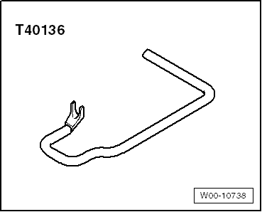
- Brake Servo Release Tool -T40136-
Caution
If possible, leave the brake pedal stop installed; it could break the mount for the Brake Lamp Switch -F- if the brake pedal is released too quickly.
Procedure
- Remove the Brake Lamp Switch -F-. Refer to → Chapter "Brake Lamp Switch, Removing and Installing".
- Press and hold the brake pedal in the direction of the brake booster.
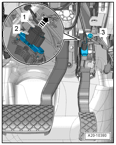
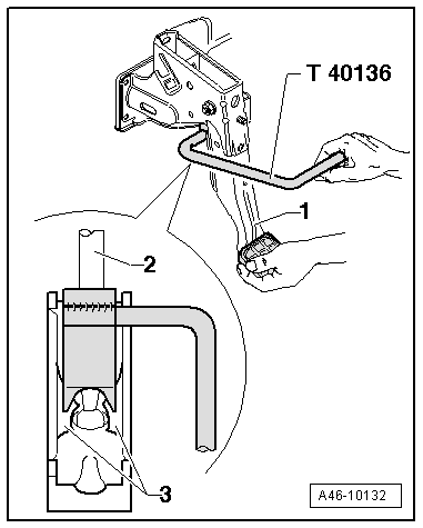
- Insert the Brake Servo Release Tool -T40136- and pull in the direction of the driver seat while counter-holding at the brake pedal -1- so that it does not move backward. While doing so, the mount retaining tabs -3- will be pushed out of the pushrod ball head -2-.
Note
The illustration shows the installation position with the pedal assembly removed.
- Pull the Brake Servo Release Tool -T40136- and the brake pedal together toward the driver seat. This will pull the brake pedal off the push rod ball head.
Brake Pedal, Attaching to Brake Booster
Procedure
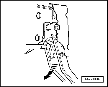
- Hold the pushrod ball head in front of the mount and push the brake pedal toward the brake booster -arrow- until the ball head engages audibly.
- Install the Brake Lamp Switch -F-. Refer to → Chapter "Brake Lamp Switch, Removing and Installing".
WARNING
Risk of accident!
Make sure the brakes are working correctly before driving the vehicle for the first time.
Brake Pedal, Removing and Installing
Special tools and workshop equipment required
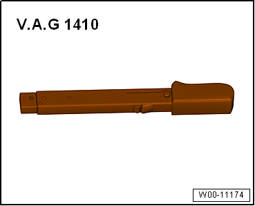
- Torque Wrench 1410 -VAG1410-
Caution
This procedure contains mandatory replaceable parts. Refer to component overview and parts catalog prior to starting procedure.
Mandatory Replacement Parts
- Clamps - Mounting pin
Removing
Vehicles with Manual Transmission:
- Remove the mounting bracket. Refer to → Chapter "Mounting Bracket, Removing and Installing".
Continuation for All Vehicles:
- Loosen the bolt -3- for the pin.
- Remove both clips -1- from the pin.
- Remove the bolt -5- from the brake pedal -2- and mounting bracket -4-.
- Remove the brake pedal.
Installing
Caution
If possible, leave the brake pedal stop installed; it could break the mount for the Brake Lamp Switch -F- if the brake pedal is released too quickly.
- Slide the right retainer onto the pins.
- Slide the pins from right to left through the axle in the brake pedal.
- Secure the pins with the left retainer -1-.
- The pins must be secured with the retainers on both sides.
- Install and tighten the bolt -3-.
- Install mounting bracket. Refer to → Chapter "Mounting Bracket, Removing and Installing".
WARNING
Risk of accident!
Make sure the brakes are working correctly before driving the vehicle for the first time.
Special Tools
Special tools and workshop equipment required
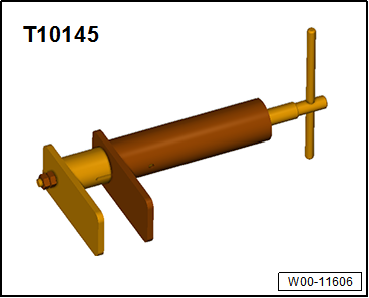
- Piston Resetting Tool -T10145-
- Brake Servo Release Tool -T40136-
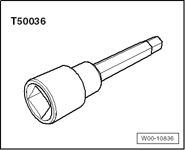
- Socket - Xzn 9 -T50036-
- Torque Wrench 1331 5-50Nm -VAG1331-
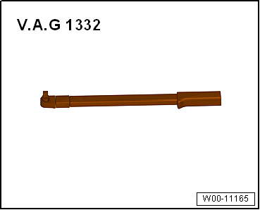
- Torque Wrench 1332 40-200Nm -VAG1332-
- Torque Wrench 1332 Insert - Reversible Ratchet -VAG1332/1-
- Torque Wrench 1410 -VAG1410-
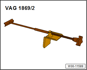
- Brake Pedal Actuator -VAG1869/2-.
- Brake Charger/Bleeder Unit -VAS5234-
- Assembly Part Set -5Q0698311-