Audi A6 Typ 4G: Peripheral Camera Control Module -J928-, Removing and Installing
The Peripheral Camera Control Module -J928- is located under the right front seat.
 Note
Note
If replacing the control module, select the "Replace Control Module" function on the Vehicle Diagnostic Tester.
Removing
- Turn off the ignition and all electrical consumers and remove the ignition key.
- Move the carpet to the side. Refer to → Body Interior; Rep. Gr.70; Passenger Compartment Trim; Carpet, Removing and Installing.
- Open the E-box cover -1-.
- Release and disconnect the connectors -arrows- from the Peripheral Camera Control Module -J928--2-.
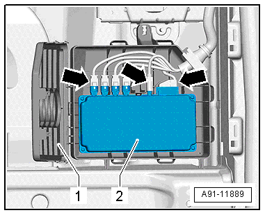
The Peripheral Camera Control Module -J928--2- is only clipped into the E-box.
- Push the retainer to the side and remove the Peripheral Camera Control Module -J928--2- from the E-box.
Installing
- Install in reverse order of removal.
- Perform a calibration. Refer to → Chapter "Peripheral Camera System, Calibrating".
Rear Peripheral Camera -R246-, Removing and Installing
Rear Peripheral Camera -R246-, Removing and Installing, Sedan
The Rear Peripheral Camera -R246- is installed in the rear lid handle button. It is permanently attached to the button.
The handle button must be replaced when replacing the Rear Peripheral Camera -R246-.
- Turn off the ignition and all electrical consumers and remove the ignition key.
Removing
The Rear Peripheral Camera -R246- has a trailing cable pig tail. The vehicle wiring harness couplings are located in the rear lid.
- Remove the rear lid trim panel. Refer to → Body Interior; Rep. Gr.70; Luggage Compartment Trim Panels; Lower Rear Lid Trim Panel, Removing and Installing.
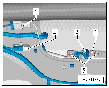
- Release and disconnect the connectors -1-, -2- and -3- in the rear lid.
The Rear Peripheral Camera -R246- is permanently attached to the handle button.
Note
Depending on the market, it may be necessary to remove the license plate or the license plate bracket.
- Remove the nuts -5-.
- Pull the handle button -4- with the Rear Peripheral Camera -R246- out of the retainer in the rear lid.
Installing
- Install in reverse order of removal.
- Close the rear lid.
The Rear Peripheral Camera -R246- must be programmed again prior to calibrating if it was replaced.
Use Vehicle Diagnostic Tester.
- Perform a calibration. Refer to → Chapter "Rear Peripheral Camera -R246-, Removing and Installing, Sedan".
Front Peripheral Camera -R243-, Removing and Installing
The Front Peripheral Camera -R243- is installed in the bumper cover between the Audi rings (between Night Vision System Camera -R212- and Garage Door Opener Control Module -J530-).
- Turn off the ignition and all electrical consumers and remove the ignition key.
Removing
- Remove the front bumper cover. Refer to → Body Exterior; Rep. Gr.63; Front Bumper; Bumper Cover, Removing and Installing.
- Remove the radiator grille from the bumper cover. Refer to → Body Exterior; Rep. Gr.63; Front Bumper; Bumper Cover, Removing and Installing.
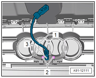
- Remove the screws -2- on the Front Peripheral Camera -R243--3-.
- Remove the Front Peripheral Camera -R243--3- from the bumper cover.
- Release and disconnect the wire -1- from the Front Peripheral Camera -R243--3-.
Installing
- Install in reverse order of removal.
The Front Peripheral Camera -R243- must be programmed again prior to calibrating if it was replaced.
Use Vehicle Diagnostic Tester.
- Perform a calibration. Refer to → Chapter "Front Peripheral Camera -R243-, Removing and Installing".