Audi A6 Typ 4G: Pyrotechnic Components Safety Precautions
 Note
Note
Pyrotechnic components:
- Airbag units
- Belt tensioner
- Belt force limiter (depending on equipment)
- Battery cut-off components (depending on equipment)
General
 Caution
- Testing, assembly, and repair work may only be performed by qualified personnel.
- There is no change interval for airbag units.
- Never test with a test light, volt meter or ohm meter.
- The pyrotechnic components may be check only when they are installed and with a Volkswagen approved vehicle diagnosis, testing and information system.
- When working on the Airbag System (pyrotechnic components, Airbag Control Module -J234-, wiring), the battery Ground (GND) cable must be disconnected WITH THE IGNITION SWITCHED ON. Then cover the negative terminal.
- Wait for 10 seconds after disconnecting the battery.
- The ignition must be SWITCHED ON when connecting the battery. Nobody should be inside the vehicle with doing this. Exception: Vehicles with a battery inside the passenger compartment.
- If the ignition is not switched on after the battery is reattached - the warning lamps on the instrument cluster do not light up - then place the ignition (button) on the driver seat, which should be reclined back to its furthest position.
- Follow the steps after connecting the battery. Refer to → Electrical Equipment; Rep. Gr.27; Battery; Battery, Disconnecting and Connecting.
- Before handling pyrotechnic components of the restraint system, for example, before disconnecting the electrical harness connector, the relevant person must discharge static electricity. Touching grounded metal parts, for example, touching the door striker, will discharge the static electricity.
- Wash hands after touching ignited restraint system pyrotechnic components.
- Pyrotechnic components may not be opened nor repaired; always use new parts (risk of injury).
- Pyrotechnic components that have fallen onto a hard surface or show signs of damage must not be installed in vehicle.
- Pyrotechnic components should be installed immediately upon removal from shipping package.
- If the work must be stopped for awhile, put the pyrotechnic component back into its shipping package.
- Do not leave the pyrotechnic component out unattended.
- When connecting restraint system pyrotechnic components, only the person performing the work should be in the vehicle.
- Do not use any grease or cleaning solutions on pyrotechnic components.
- Replace the airbag unit if any contaminants such as oil, grease, paint, dye or cleaning solution have penetrated the fabric.
- Pyrotechnic components must not be exposed to temperatures over 100 ºC (212 ºF), even for a short time.
Special Information Regarding the Driver and Front Passenger Airbags
- Store the driver and front passenger airbag units in the uninstalled state so that the cushioned side faces upward.
When replacing airbag units, following sequence must be followed exactly:
1 - Remove the old airbag unit and store with the upholstered side facing up.
2 - Remove the new airbag unit from the transport container and store it with the upholstered side facing up.
3 - Place the old airbag unit in the transport container immediately.
4 - Install the new airbag unit in the vehicle.
Belt Tensioner Special Instructions
- Use extreme care when removing and installing belt tensioners. Handling belt tensioner units improperly is very dangerous and could result in serious personal injury.
- Belt tensioners that are mechanically damaged (dents, cracks) must always be replaced.
- The open end of the belt tensioner should never be pointed at anyone.
- When connecting a belt tensioner, all mechanical parts, including those in the three-point seat belt, must be secured correctly. If it is not possible to connect the belt tensioner because of insufficient space, the seat belt must be rolled up completely prior to connection. In this case there is no increased safety risk, if all other safety instructions are followed. In particular, this includes the notes regarding the disconnection of the battery and the static discharging of the technician prior to connection of the belt tensioner.
- Even after a crash, it is possible that the belt tensioner ignited, but the belt force limiter did NOT. Treat these components as if they had not ignited!
High Voltage Vehicles Safety Precautions
 WARNING
The engine could start unexpectedly.
For general work performed on the high voltage system the ignition must be switched off and the key must be kept outside of the vehicle interior.
DANGER!
When working on vehicles with the ignition already switched on or that are ready to drive there is a danger of the engine starting unexpectedly and of being poisoned by gas in enclosed areas. Risk of body parts and/or clothing being clamped or pulled.
Perform the following before switching on the ignition:
- Move the selector lever into P.
- Activate the parking brake
- Turn off the ignition.
- Open the hood
- Connect the charger, such as the Battery Charger -VAS5095A- to the jump start of the 12V vehicle electrical system.
- Turn on the ignition.
DANGER!
High voltage components have hazardous voltage.
Note the following when working near high voltage components and high voltage cables:
- Cutting, deformed, and sharp edged tools or heat sources such as welding, solder, hot air and thermal glue are forbidden.
- Visually inspect the work area before working on high voltage components.
- Perform a visual inspection of the Electric Drive Power and Control Electronics -JX1-, the Electro-Drive Drive Motor -V141-, the Electrical A/C Compressor -V470- and the high voltage lines when working in the engine compartment.
- Visually inspect the high voltage cables and the covers when working on the underbody.
- Visually inspect the high voltage cables, the electronics and the High Voltage System Maintenance Connector -TW -, when working in the luggage compartment.
- Visually inspect all potential equalization cables.
Observe the following when performing the visual inspection:
- None of the components appear to have any external damage.
- The high voltage cable insulation and the potential equalization cable insulation are not damaged.
- The high voltage cables must not have any unusual deformations.
- Each high voltage component must be marked with a red warning label.
Start/Stop System Safety Precautions
Pay attention to the following when working on a vehicle with Stop/Start system:
WARNING
There is a risk of injury if the engine starts automatically in vehicles with the Start/Stop system.
- For vehicles with an activated Start/Stop system (recognized by a signal in the instrument cluster), the engine can be started automatically if needed.
- Make sure that the Start/Stop system is deactivated when working on the vehicle (turn off the ignition, turn on the ignition when necessary).
Airbag, Belt Tensioner and Battery Cut-Out Units, Storing, Transporting and Disposing
- Storage must conform to national legislation.
- Transport must conform to national and international guidelines, whereby packaging, identification and shipping documents are controlled to the greatest detail.
- Undeployed pyrotechnic components must be disposed of in an orderly manner, conforming to national legislation, in their original packaging! Direct questions to your importer.
- Only pyrotechnic components, which have been ignited completely, may be disposed in industrial waste.
WARNING
- This does not apply to belt tensioners that function according to the Wankel pretensioner principle. These are to be treated like undeployed pyrotechnic components (such as airbags, seat belts, pyrotechnic battery components).
- Workshop equipment cannot determine if Wankel belt tensioners have deployed all pyrotechnic materials.
Side Airbag Additional Safety Precautions
Caution
- We recommend using original equipment seat covers.
- Seat covers or extra covers that are not approved specially for use on Audi seats with side airbags must not be used.
- Do not cut the backrest material in side airbag area.
- When installing, seam in side airbag region must run straight.
- All cushion clips have to be replaced (metal and plastic clips).
- Using original equipment upholstery clips is recommended.
- During installation, all upholstery clips must be placed in the same place they were when they were removed.
- If cover is damaged (with rips, burned holes, etc.) in side airbag region, it must be replaced for safety reasons so that airbag deploys correctly.
- Do not repair the backrest cover in the side airbag area (because of special materials and strictly defined seams).
- Always replace the backrest padding if the side airbag deploys.
- After an accident, all damaged parts must be replaced. If no airbag unit damage is detected, the unit can still be used.
- If thorax airbag units are replaced, the new thorax airbag number sticker should be removed and placed over the old sticker on the seat pan.
- Do not poke the cover with an upholstery needle or other sharp objects near the airbag, the Front Passenger Occupant Detection Sensor -G128- or the passenger occupant detection system mat.
Head Curtain Airbag Additional Safety Precautions
Caution
- Visually check trim for damage before installing.
- Do not make any repairs to the trims (upper A-pillar trim, B-pillar trim, C-pillar trim, and D-pillar trim).
- Ensure secure trim seating when installing.
- Replace entire module when making repairs behind side curtain airbag.
- Handle head curtain airbag modules with great care when removing and installing them to prevent causing any damage.
- Place any removed head curtain airbag modules back in their transport containers or on a clean and even surface with a cloth underneath.
- After servicing the body in the vicinity of the head curtain airbag, check the body for welding beads, deformation and chafe marks (compare with opposite side of vehicle if necessary).
- As long as the gas generator is NOT attached, hold it securely when transporting, removing, installing, etc.
- Never rotate, coil, knot, throw, slide, push, hang, squeeze, press, pinch or clamp head curtain airbag module.
- They may be folded as long as this does not damage them, especially the protective sleeve.
Front Side Airbag Crash Sensors (Pressure Sensors) Safety Precautions
Crash sensors for side airbags react to changes in pressure and therefore must be handled extremely carefully. Note the following points:
Caution
- Always use the correct installation position and only install in the location intended in the doors.
- Protect the crash sensor from impact. Do not use a crash sensor if it has fallen on the floor. When doing body work on the door, the crash sensor should be removed.
- The crash sensor is calibrated to the volume of air inside the door. If the door is deformed resulting in a reduced air space inside the door, the function of the crash sensor will be affected.
- Avoid contamination of the crash sensor. Do not use compressed air in the area surrounding the crash sensor. Protect crash sensor from filings or shavings (for example, when installing door speakers later). Do not use cavity sealant or spray lubricant in the area of the crash sensor.
- Protect against heat and cold. Avoid heating, for example when painting or doing other body work. Crash sensors should not be subjected to temperatures below -40 ºC (-40 ºF) (for example, in non-climate-controlled airplane cargo holds).
- Protect the crash sensor from moisture when storing or installing it.
For failure-free crash sensor function, effective door seal must be guaranteed after installation. Note the following points:
- All components (for example, cover, speaker, door trim) must be installed correctly.
- The door trim clips seal the system. If necessary, replace retaining clips.
Passenger Occupant Detection System Deactivation Additional Safety Precautions, Market-Specific
Caution
- After each repair to the front passenger seat where the seat or backrest cover was "removed", a basic setting of the passenger occupant detection system control module must be performed using the Vehicle Diagnostic Tester.
- Do not bend the passenger occupant detection system mat.
- A leaking mat must be replaced (service kit).
- Do not bend the passenger occupant detection system pressure hose.
- Make sure the components of the passenger occupant detection system do not fall onto hard surfaces, do not come into contact with grease and do not risk damage by resting against sharp objects.
- The mat, the fleece and various covers must be fitted to be free of folds.
- Make sure the seat padding and cover are positioned correctly when installing.
- Replace all upholstery clips or clips and make sure they are positioned correctly on the seat. Be careful not to damage or clip the glued/sewn passenger occupant detection sensor with the upholstery clips.
- The system basic setting can be performed at temperatures between 0 ºC and 40 ºC (32 ºF and 104 ºF) with 8.R and 9.* airbags. The temperature must be between 5º and 35 ºC (41º and 95 ºF) with 10.* airbags.
- Make sure that no objects are placed on seat when performing basic setting.
- The use of additional seat cushions such as pillows impairs the function of the passenger occupant detection system and the operation of the airbag system.
- The seat and all the passenger occupant detection system components must be dry when being installed. Moisture will negatively affect the passenger occupant detection system. If necessary, let the seat, the seat cushion, the passenger occupant detection sensor and the seat cover dry out first.
- Never disconnect the connector between the Passenger Occupant Detection System Control Module and the Front Passenger Seat Occupant Sensor. Refer to → Chapter "Component Location Overview - Passenger Occupant Detection System".
- Do not pull on the passenger occupant detection sensor wire.
- Standard seat/Sport seat/Super Sport seat: The passenger occupant detection sensor is glued to the seat cushion or the seat heating element on a replacement seat (Service Kit). Make sure there adhesive is smooth before installation, if necessary.
- Multi-contour seat: the passenger occupant detection sensor for the passenger occupant detection system with seat heating element is sewn inside the seat cover on a replacement seat (Service Kit). Only the seat cover is replaced. Do not twist the seat cover.
Passenger Occupant Detection System Deactivation After a Collision, Market-Specific
- Each time an airbag or passenger belt tensioner deploys, a basic setting must be performed on the passenger occupant detection system control module. Refer to Vehicle Diagnostic Tester.
- If the seat rails and/or seat pan is replaced after an accident due to deformations resulting from a crash, the passenger occupant detection system must be replaced using the "passenger occupant detection system service kit". Perform a "basic setting" on the passenger occupant detection system control module using the Vehicle Diagnostic Tester.
Passenger Safety System Pyrotechnical, Electric and Mechanical Components, Replacing After a Collision
Special tools and workshop equipment required
- Vehicle Diagnostic Tester
Note
- The airbag control module can be used for up to two deployments of the side, driver and passenger airbag and/or belt tensioner with airbag generation 8.* "not 8.R".
- The airbag control module can be used for up to two side, driver and passenger airbag and/or belt tensioner deployments with airbag generation 9.*, 10.* and 8.R.
- After the third deployment, the malfunction display "Control module defect" appears.
Airbag Control Module Must Be Replaced
- With driver and passenger airbag deployment "but not with airbag generation 9.*, 10.* and 8.R".
- After three side, driver, and passenger airbag or belt tensioner deployments
- If housing is damaged
- If there is deformation on tunnel in 200 mm circumference around control module
- Always Replace the Following
- All triggered airbag units
- The Battery Interrupt Igniter -N253-
Also with Passenger Airbag Deployment
- Instrument Panel
- Deformed passenger module supports (cannot be reformed)
- All sensors for front airbag on front end
- Remaining cross acceleration sensors if anchorage point is deformed in sensor region
Also with Driver Airbag Deployment:
- Coil connector with slip ring
- All sensors for front airbag on front end
- Remaining cross acceleration sensors if anchorage point is deformed in sensor region
Also with Side Airbag Deployment:
- Pressure sensors on deployed side
- Cross acceleration sensors on deployed side
- Cover
- Cushion
- With a folding rear seat backrest: side cushion (if equipped)
- Remaining cross acceleration sensors if anchorage point is deformed in sensor region
In Addition
- All automatic belt retractors with deployed belt tensioners.
- All automatic belt retractors with deployed seat belt force limiters (depending on vehicle equipment).
- Seat belt latches for all automatic belt retractors with deployed seat belt tensioners with the belt on
- Seat belt height adjuster (manual and power) for all automatic belt retractors with deployed seat belt tensioners with the belt on
- Connect the Vehicle Diagnostic Tester if there is a chance the belt tensioner and/or seat belt force limiter deployed.
- In "guided fault finding" under "15 - Airbag", check whether there is a crash entry in the airbag control module.
- Also check if the "Resistance too large" error is stored for the belt tensioner and/or belt force limiter. Deployed belt tensioners and/or belt force limiters must fulfill both conditions. "Prerequisite: the airbag control module was not replaced yet".
Note
- The "Resistance too large" error may also be stored if there is an open circuit. Then there is no crash entry.
- Depending on the crash, the belt tensioner may have deployed while the belt force limiter did "NOT". In that case, follow the disposal information for pyrotechnic components. Refer to → Chapter "Airbag, Belt Tensioner and Battery Cut-Out Units, Storing, Transporting and Disposing".
- Also check the seat belts. Refer to → Chapter "Seat Belts, Checking".
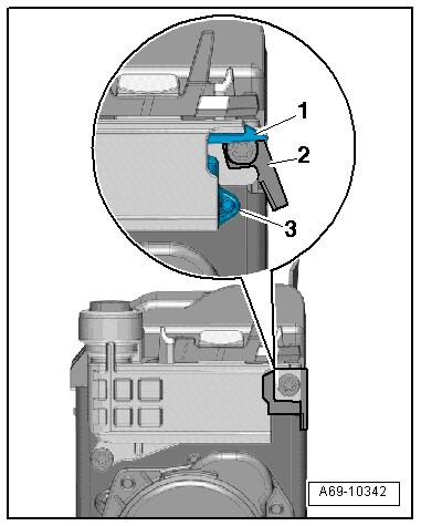
- Deployed belt force limiters can be recognized by the following characteristics:
- The pin -1- and tab -3- are protruding out of the belt force limiter housing on the automatic belt retractor.
- The tab -2- is no longer vertical but is diagonal toward the outside.
- If parts of the seat belt system are removed due to an accident, replace the belt system bolts.
- If needed (visual inspection), the following must also be replaced: all faulty components.
- After replacing the airbag units or the control module, affix stickers (only tear-off strips) to the registration card and return the registration card to the relevant Sales Center or to the Importer for registration.