Audi A6 Typ 4G: Component Location Overview - Storage Compartment/Covers
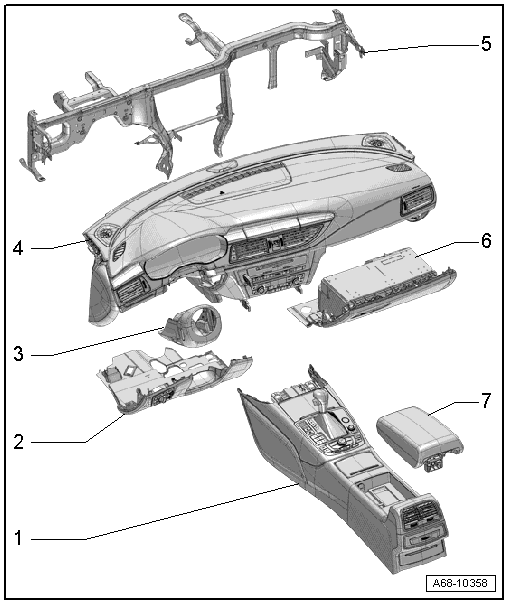
1 - Center Console
- Overview. Refer to → Chapter "Overview - Center Console".
2 - Driver Side Instrument Panel Cover
- Overview. Refer to → Chapter "Overview - Driver Side Instrument Panel Cover".
3 - Trim Panel
- For the steering column switch module
- Overview. Refer to → Chapter "Overview - Steering Column Trim Panel".
4 - Instrument Panel
 WARNING
Follow all Safety Precautions when working with pyrotechnic components. Refer to → Chapter "Pyrotechnic Components Safety Precautions".
- Overview. Refer to → Chapter "Overview - Instrument Panel".
5 - Central Tube
- For the instrument panel
- Overview. Refer to → Chapter "Overview - Instrument Panel Central Tube".
6 - Glove Compartment
- Overview. Refer to → Chapter "Overview - Glove Compartment".
7 - Front Center Armrest
- Overview. Refer to → Chapter "Overview - Front Center Armrest".
Overview - Driver Side Instrument Panel Cover
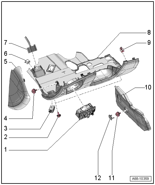
1 - Light Switch -E1-
- Removing and installing. Refer to → Electrical Equipment; Rep. Gr.96; Controls; Overview - Instrument Panel Controls.
2 - Bolt
- 3 Nm
- Quantity: 2
3 - Left Front Footwell Illumination Bulb -L151-
- Equipment levels
- Removing and installing. Refer to → Electrical Equipment; Rep. Gr.96; Lamps; Left/Right Front Footwell Illumination Bulb L151/L152, Removing and Installing
4 - Bolt
- 3 Nm
5 - Side Cover
- For the instrument panel
- Removing and installing. Refer to → Chapter "Instrument Panel Side Cover, Removing and Installing".
6 - Clip
- Install in the foot rest
7 - 16-Pin Connector -T16-
- Data Link Connector (DLC)
8 - Driver Side Instrument Panel Cover
- Removing and installing. Refer to → Chapter "Driver Side Instrument Panel Cover, Removing and Installing".
9 - Spring Clip
- For the driver side instrument panel cover
- Quantity: 5
- Different version. For allocation. Refer to the Parts Catalog
- Replace damaged or deformed spring clips
- Press correctly into the instrument panel
10 - Lower Cover
- For the instrument panel
- Removing and installing. Refer to → Chapter "Front Footwell Cover, Removing and Installing".
- Replace damaged or deformed spring clips on the Air Conditioning (A/C) System
11 - Bolt
- 3 Nm
12 - Cap
- Press into the cover
Overview - Steering Column Trim Panel
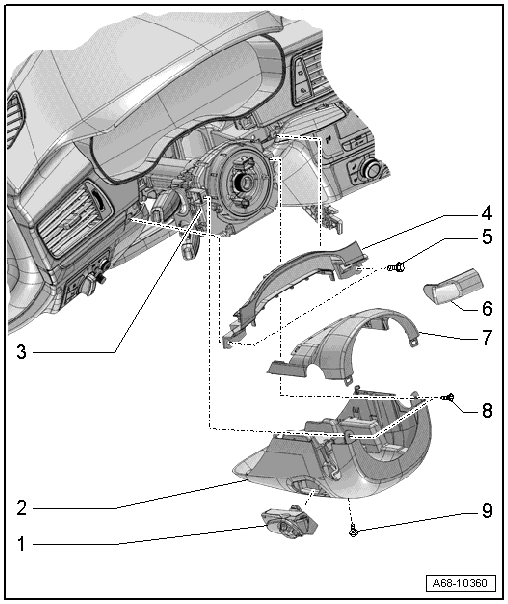
1 - Steering Column Adjustment Switch -E167-
- Equipment levels
- Removing and installing. Refer to → Electrical Equipment; Rep. Gr.96; Controls; Steering Column Adjustment Switch E167 and Steering Wheel Heating Button E522, Removing and Installing
2 - Lower Trim Panel
- For the steering column switch module
- Removing and installing. Refer to → Chapter "Lower Steering Column Trim Panel, Removing and Installing".
3 - Steering Column Switch Module
- Removing and installing. Refer to → Electrical Equipment; Rep. Gr.94; Steering Column Switch Module; Steering Column Switch Module, Removing and Installing.
4 - Gap Cover
- For instrument cluster
- Removing and installing. Refer to → Chapter "Instrument Cluster Gap Cover, Removing and Installing".
- Press on until it engages audibly.
5 - Bolt
- 3 Nm
- Quantity: 2
6 - Gap Cover
- For the instrument panel
- Quantity: 2
- Removing and installing. Refer to → Chapter "Instrument Cluster Gap Cover, Removing and Installing".
7 - Upper Trim Panel
- For the steering column switch module
- Removing and installing. Refer to → Chapter "Upper Steering Column Trim Panel, Removing and Installing".
8 - Bolt
- 1.5 Nm
- Quantity: 2
9 - Bolt
- 1.5 Nm
Overview - Glove Compartment
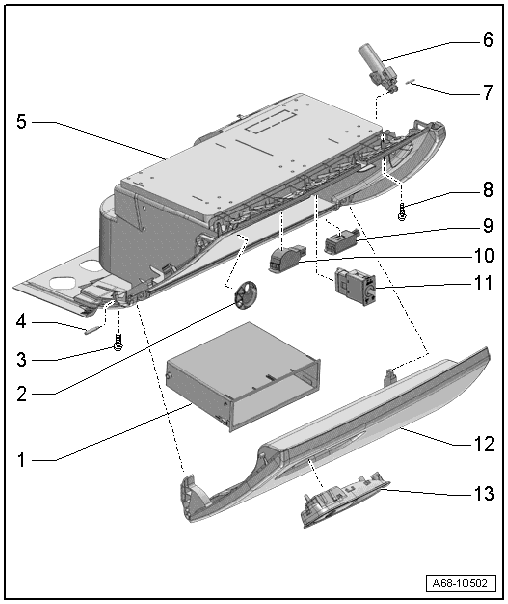
1 - Storage Compartment
- Equipment levels
- Removing and installing. Refer to → Chapter "Storage Compartment, Removing and Installing".
2 - Cold Air Vent/Blind Cover
- Equipment levels
3 - Bolt
- 3 Nm
- Quantity: 2 or 3 depending on the equipment level
- Quantity: 3, for market versions with knee airbag
4 - Hinge Pin
- Quantity: 2
- For the glove compartment lid
5 - Glove Compartment
- Removing and installing. Refer to → Chapter "Glove Compartment, Removing and Installing".
6 - Brake Component
- For the glove compartment lid
- With Glove Compartment Lamp Switch -E26-
- Removing and installing. Refer to → Chapter "Glove Compartment Lid Dampening Mechanism, Removing and Installing".
7 - Hinge Pin
- For the brake component
8 - Bolt
- 3 Nm
- Quantity: 3, for market versions without knee airbag
- Quantity: 5, for market versions with knee airbag
9 - Right Front Footwell Illumination Bulb -L152-
- Equipment levels
- Removing and installing. Refer to → Electrical Equipment; Rep. Gr.96; Lamps; Left/Right Front Footwell Illumination Bulb L151/L152, Removing and Installing
10 - Glove Compartment Lamp -W6-
- Removing and installing. Refer to → Electrical Equipment; Rep. Gr.96; Lamps; Glove Compartment Lamp W6, Removing and Installing.
11 - Front Passenger Airbag Deactivation Key Switch -E224-
Not for North American market.
12 - Glove Compartment Cover
- Activate the glove compartment cover emergency release. Refer to → Chapter "Glove Compartment Lid Emergency Release, Operating".
- Removing and installing. Refer to → Chapter "Glove Compartment Lid, Removing and Installing".
13 - Glove Compartment Opener
- Removing and installing. Refer to → Chapter "Glove Compartment Handle, Removing and Installing".
- Press into the glove compartment cover until it engages audibly
- Market-specific with knee airbag: with additional threaded connection → Fig. "Glove Compartment Handle with Additional Threaded Connection, Vehicle Versions with Knee Airbag"
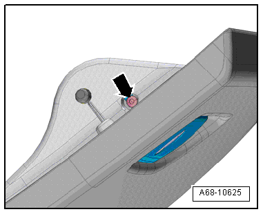
Glove Compartment Handle with Additional Threaded Connection, Vehicle Versions with Knee Airbag
- Tighten the screw -arrow- to 1.8 Nm.