Audi A6 Typ 4G: Rear Final Drive, Disassembling and Assembling
Hydraulic Control Unit, Removing and Installing
 Note
Note
- Follow the general repair information. Refer to → Chapter "General Repair Information".
- Pay attention to the safety precautions. Refer to → Chapter "Safety Precautions and Test Procedures".
Removing
- The ignition is off.
- Place the vehicle on a lift.
- Lower the back section of the exhaust system just a little and secure it. If necessary remove the back section of the exhaust system.
Note
A second technician is needed to help remove the rear section of the exhaust system.
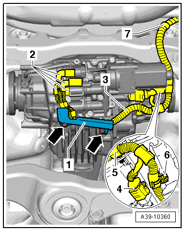
- If equipped, remove the bolts -arrows- and remove the wiring harness bracket -1- from the rear final drive.
Note
Mark the Oil Pressure/Temperature Sensor and the Clutch Valves connectors -2-.
- Disconnect the connectors -2- from the Oil Pressure/Temperature Sensor and the Clutch Valves.
- Disconnect the connector -4- from the All Wheel Drive Pump -V415-.
- Unclip the wiring harness -3- from the final drive and the subframe and tie it up -5 through 7-.
- Place the Drip Tray under the rear final drive.
- Drain the ATF from the rear final drive. Refer to → Chapter "ATF on Rear Final Drive 0BF and 0BE, Draining".
- Drain the gear oil from the rear final drive. Refer to → Chapter "Gear Oil on Rear Final Drive 0BF and 0BE, Draining".
- Remove the All Wheel Drive Pump -V415-. Refer to → Chapter "All Wheel Drive Pump -V415-, Removing and Installing".
Note
The All Wheel Drive Pump -V415- must be removed in order to loosen and tighten the nut on the right line to the hydraulic control unit.
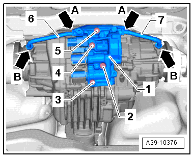
- Loosen the left -6- and right -7- lines to the hydraulic control unit -1- one turn -arrows A- and remove them from the chambers -arrows B-.
- Remove the bolts -2 through 5- and remove the hydraulic control unit -1- with the seal.
Installing
Note
Follow all safety precautions exactly when replacing the hydraulic control unit. Install the "old" sensors again if possible. Refer to → Chapter "Safety Precautions and Test Procedures".
Conditions
- Replace the seal between the hydraulic control unit -1- and the final drive housing.
- The centering pins -item 18- must be installed inside the housing for the hydraulic control unit.
- The left -6- and right -7- lines must be installed loosely when attaching the hydraulic control unit -1-.
Attach the hydraulic control unit -1- to the rear final drive as follows:
First install the lines -6 and 7- into the chambers hand-tight -arrows B-.
Then install the bolts -2 through 5- hand-tight. One bolt -2- has a permanent seal on the head. Coat the thread with Sealing Compound -D 176 501 A1-.
Tighten the M8 x 30 bolts -2 through 5- to the tightening specification in the sequence: -4, 2, 5 and 3-.
Tighten the nuts -A arrows- and -B arrows- on the left -6- and right -7- lines to the tightening specification.
- Install the All Wheel Drive Pump -V415-. Refer to → Chapter "All Wheel Drive Pump -V415-, Removing and Installing".
- Install the wiring harness -3- to the final drive and subframe -5 through 7-.
- Connect the connectors -4 and 2-. Pay attention to the marks made during the removal, that identify the allocation to the Oil Pressure/Temperature Sensor and which connectors go to the Clutch Valves.
- If equipped, position the wiring harness bracket -1- on the rear final drive and tighten the bolts -arrows- to the tightening specification. Make sure the wiring harness -3- does not get pinched.
Note
- Allocation for the Oil Pressure/Temperature Sensor and Clutch Valves connectors:
- -1- = Oil Pressure/Temperature Sensor 2 -G640- Connector
- -2- = Oil Pressure/Temperature Sensor -G437- Connector
- -3- = All Wheel Drive Clutch Valve 2 -N446- Connector
- -4- = All Wheel Drive Clutch Valve -N445- Connector
- Fill the rear final drive with gear oil and then check the level. Refer to → Chapter "Gear Oil Level in Rear Final Drive 0BF and 0BE, Checking".
- Fill with ATF in the rear final drive and check the ATF level. Refer to → Chapter "ATF Level in Rear Final Drive 0BF and 0BE, Checking".
- Install the rear section of the exhaust system and align it so it is free of tension.
Hydraulic Control Unit, Disassembling and Assembling
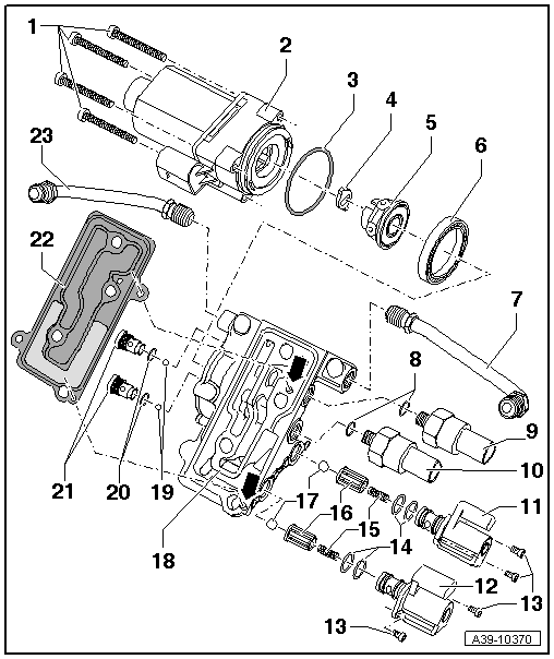
1 - Bolt
- 5 Nm
2 - All Wheel Drive Pump -V415-
- Removing and installing. Refer to → Chapter "All Wheel Drive Pump -V415-, Removing and Installing".
3 - O-Ring
- Always replace.
4 - Adapter
Note
- The adapter could fall out when removing the All Wheel Drive Pump -V415-.
- Insert the adapter into the recesses in the hydraulic pump before installing the All Wheel Drive Pump -V415-.
5 - Hydraulic Pump
- Consists of a guide ring, the housing and six pistons
- Assembling. Refer to → Fig. "Assembling the Hydraulic Pump"
6 - Ball Bearing
- Can be installed and removed by hand
7 - Left Line
- Tighten the nuts to 30 Nm.
- Is installed between the hydraulic control unit and the left chamber
- Tighten both nuts hand-tight when installing
8 - O-Ring
- Always replace.
9 - Oil Pressure/Temperature Sensor -G437-
- 10 Nm
- Brown connector
- Removing and installing. Refer to → Chapter "Oil Pressure/Temperature Sensor -G437- or Oil Pressure/Temperature Sensor 2 -G640-, Removing and Installing".
10 - Oil Pressure/Temperature Sensor 2 -G640-
- 10 Nm
- Black connector
- Removing and installing. Refer to → Chapter "Oil Pressure/Temperature Sensor -G437- or Oil Pressure/Temperature Sensor 2 -G640-, Removing and Installing".
11 - All Wheel Drive Clutch Valve 2 -N446-
- Color: brown
- Removing and installing. Refer to → Chapter "All Wheel Drive Clutch Valve -N445- or All Wheel Drive Clutch Valve 2 -N446-, Removing and Installing".
- Installed position, the connector faces upward toward the Oil Pressure/Temperature Sensor
 Caution
Do not interchange with the All Wheel Drive Clutch Valve -N445-.
12 - All Wheel Drive Clutch Valve -N445-
- Color: black
- Removing and installing. Refer to → Chapter "All Wheel Drive Clutch Valve -N445- or All Wheel Drive Clutch Valve 2 -N446-, Removing and Installing".
- Installed position, the connector faces upward toward the Oil Pressure/Temperature Sensor
Caution
Do not interchange with the All Wheel Drive Clutch Valve 2 -N446-.
13 - Bolt
- 2.5 Nm
14 - O-Ring
- Always replace.
- Mount onto the Clutch Valve
15 - Pressure Spring
- Insert into the guide -item 16-
16 - Guide
- Installation position, large diameter faced the ball -item 17-
17 - Ball
- Insert into the guide before installing -item 16-
18 - Hydraulic Control Unit Housing
- With centering pins -arrows-
- The centering pins lock the hydraulic control unit and seal to the final drive housing.
19 - Ball
- Install in the hole in the shuttle valve before installing -item 21-
20 - O-Ring
- Always replace.
21 - Shuttle Valve
- 8 Nm
- Removing and installing. Refer to → Fig. "Removing and Installing the Shuttle Valves".
22 - Gasket
- With strainer
- Install on the centering pins in the hydraulic control unit housing
23 - Right Line
- Tighten the nuts to 30 Nm.
- Is installed between the hydraulic control unit and the right chamber
- Tighten both nuts hand-tight when installing
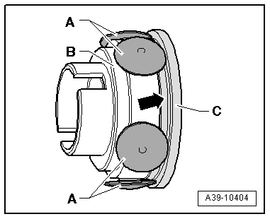
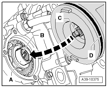
Assembling the Hydraulic Pump
- Install the six pistons -A- in the housing -B-.
- Install the guiding ring -C- so that the piston touches the collar -arrow-.
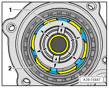
- Insert the hydraulic pump -1- with the guide ring -2- in the in the hydraulic control unit housing.
Function Test
- Turn the hydraulic pump -1- several times. While doing so pay attention to the following:
- When turning the hydraulic pump must not become hooked or tilted.
- All pistons must be removed and pressed in.
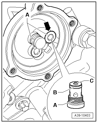
Removing and Installing the Shuttle Valves
Note
Remove the All Wheel Drive Pump -V415-, hydraulic pump and ball bearing -item 6- beforehand.
- Remove the shuttle valves -A-. Always remove the ball -C- as well.
- Insert the ball into the hole in the shuttle valve when installing.
- Install the shuttle valve all the way with a new O-ring -B-.
- The shuttle valve must rest lower than the opposing housing surface -arrow-. If this is not the case, then remove the valve again and adjust the position of the ball.
- Tighten the shuttle valve to the tightening specification -item 21-.
All Wheel Drive Pump -V415-, Removing and Installing
Special tools and workshop equipment required
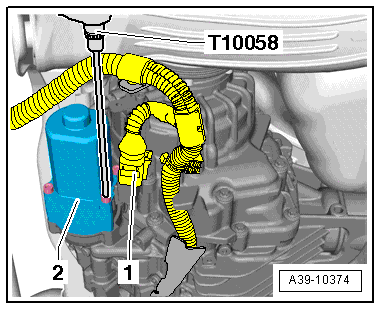
- Hex Ball Socket -T10058-
Note
- Follow the general repair information. Refer to → Chapter "General Repair Information".
- Pay attention to the safety precautions. Refer to → Chapter "Safety Precautions and Test Procedures".
Removing
- Place the vehicle on a lift.
- The ignition is off.
- Place the Drip Tray under the rear final drive.
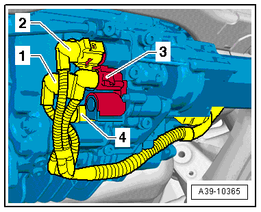
- Disconnect the connector -1- from the All Wheel Drive Pump -V415--2-.
- Remove the four bolts that connect the All Wheel Drive Pump -V415- to the hydraulic control unit using the Hex Ball Socket -T10058-.
- Carefully remove the All Wheel Drive Pump -V415--2-. Pay close attention to the adapter -item 4- inside the hydraulic pump while doing this.
Note
- The adapter could fall out when removing the All Wheel Drive Pump -V415-.
- Insert the adapter into the recesses in the hydraulic pump before installing the All Wheel Drive Pump -V415-.
Installing
- The hydraulic pump -A- is installed inside the hydraulic control unit. Assembling the hydraulic pump. Refer to → Fig. "Assembling the Hydraulic Pump".
- The adapter -B- is installed in the recesses in the hydraulic pump.
- A new O-ring -D- is on the All Wheel Drive Pump -V415-.
- Install the All Wheel Drive Pump -V415- with the coupling -C- in the adapter -B-.
- Diagonally tighten the four bolts on the All Wheel Drive Pump -V415--2- to the tightening specification -item 1-.
- Connect the connector -1- to the All Wheel Drive Pump -V415-.
- Fill with ATF in the rear final drive. Refer to → Chapter "ATF on Rear Final Drive 0BF and 0BE, Filling".
Oil Pressure/Temperature Sensor -G437- or Oil Pressure/Temperature Sensor 2 -G640-, Removing and Installing
Special tools and workshop equipment required
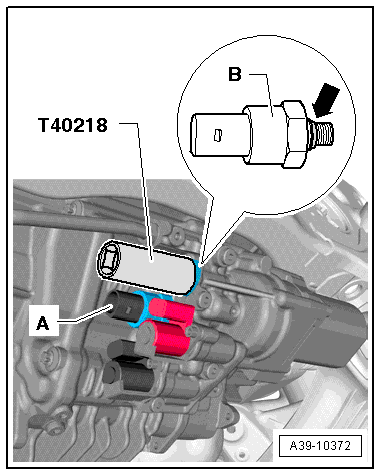
- Socket - 27mm -T40218-
- Vehicle Diagnostic Tester
Important Safety Precautions
- The identity of the sensor in the All Wheel Drive Control Module -J492- must be adapted using the Vehicle Diagnostic Tester or the Oil Pressure/Temperature Sensor 2 -G640-.
- Do not replace both the Oil Pressure/Temperature Sensor -G437- and Oil Pressure/Temperature Sensor 2 -G640- at the same time because a valid sensor identity is needed for the rear final drive classification to the All Wheel Drive Control Module -J492-. If the both sensors are replaced at the same time, the All Wheel Drive Control Module -J492- will interpret this as the rear final drive is being replaced. By doing this, adaptation values in the control module will be erased and the performance of the rear final drive will be impaired.
- If both the Oil Pressure/Temperature Sensor -G437- and the -G640- must be replaced due to mechanical damage, for example, if the connector housing gets damaged, then this must be performed in two steps. After replacing the first sensor, the identity must be adapted in the All Wheel Drive Control Module -J492- using the Vehicle Diagnostic Tester. Do the same for the second sensor.
- If both the Oil Pressure/Temperature Sensor -G437- and Oil Pressure/Temperature Sensor 2 -G640- must be replaced at the same time due to an electrical fault, then the clutch classification must be entered into the All Wheel Drive Control Module -J492- using the Vehicle Diagnostic Tester. Also, the ATF in the rear final drive must be replaced. Refer to → Chapter "ATF on Rear Final Drive 0BF and 0BE, Draining".
Note
- Follow the general repair information. Refer to → Chapter "General Repair Information".
- Pay attention to the safety precautions. Refer to → Chapter "Safety Precautions and Test Procedures".
Removing
- The ignition is off.
- Place the vehicle on a lift.
- Lower the back section of the exhaust system just a little and secure it.
- Remove the wiring harness bracket from the rear final drive, if necessary.
- Disconnect the connector -1- from the Oil Pressure/Temperature Sensor 2 -G640- and the connector -2- from the Oil Pressure/Temperature Sensor -G437-.
Note
Disconnect connectors -3 and 4- if necessary.
- Place the Drip Tray under the rear final drive.
- Remove the Sensor with the Socket - 27mm -T40218-.
-A- = Oil Pressure/Temperature Sensor 2 -G640- black connector
-B- = Oil Pressure/Temperature Sensor -G437- brown connector
Installing
- Install the new Sensor with a new O-ring -arrow- and tighten to the tightening specification -item 9- or -item 10-.
-A- = Oil Pressure/Temperature Sensor 2 -G640- black connector
-B- = Oil Pressure/Temperature Sensor -G437- brown connector
- Disconnect the connector -1- on the Oil Pressure/Temperature Sensor 2 -G640- and the connector -2- on the Oil Pressure/Temperature Sensor -G437-.
Note
Connect connectors -3 and 4- if they were disconnected earlier.
- Attach the wiring harness bracket to the rear final drive if it was removed earlier.
- Connect the Vehicle Diagnostic Tester and switch on the ignition.
- On the Vehicle Diagnostic Tester select the function 22 - Control Module, Replacing under Guided Functions in the directory 22 - Adapt Sensor.
- Follow the instructions given by the Vehicle Diagnostic Tester exactly.
"Adapt" the new sensor to the All Wheel Drive Control Module -J492- with the Vehicle Diagnostic Tester.
Note
A system check will take place when the 22 - Sensor Programing function is complete. If malfunctions appear, then use "Guided Fault Finding" to correct them.
- Fill with ATF in the rear final drive. Refer to → Chapter "ATF on Rear Final Drive 0BF and 0BE, Filling".
- Attach the rear section of the exhaust system to the body and align it so that it is free of tension.
All Wheel Drive Clutch Valve -N445- or All Wheel Drive Clutch Valve 2 -N446-, Removing and Installing
Special tools and workshop equipment required
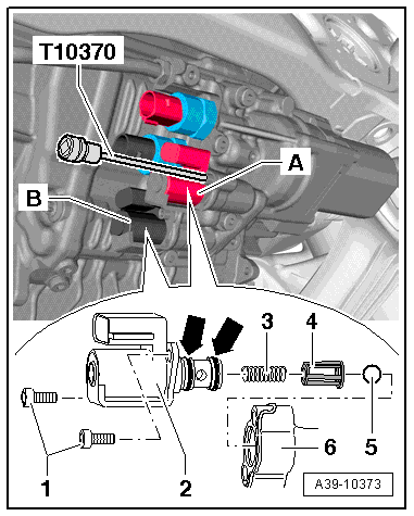
- Hex Socket - 4mm -T10370-
Note
- Follow the general repair information. Refer to → Chapter "General Repair Information".
- Pay attention to the safety precautions. Refer to → Chapter "Safety Precautions and Test Procedures".
Caution
Malfunctions on the rear final drive.
Do not confuse the All Wheel Drive Clutch Valve -N445- component location with the All Wheel Drive Clutch Valve 2 -N446- component location.
Removing
- The ignition is off.
- Place the vehicle on a lift.
- Lower the back section of the exhaust system just a little and secure it.
- Remove the wiring harness bracket from the rear final drive.
Note
- Mark the connectors -1 through 4- for the Oil Pressure/Temperature Sensor and for the Clutch Valves.
- Disconnect the connectors -1 and 2-.
- Disconnect the connector -3- from the All Wheel Drive Clutch Valve 2 -N446- and the connector -4- from the All Wheel Drive Clutch Valve -N445-.
- Place the Drip Tray under the rear final drive.
- Remove the bolts -1- from each of the Clutch Valves using the Hex Socket - 4mm -T10370-.
- Carefully pry out the Clutch Valve with a flat blade screwdriver -3-. Be careful of the pressure spring when doing this. The pressure spring could fall out of the opening in the hydraulic control unit -6-.
-A- = All Wheel Drive Clutch Valve 2 -N446- identification color brown
-B- = All Wheel Drive Clutch Valve -N445- identification color black
Installing
- The ball -5-, the guide -4- (the smaller diameter faces the spring) and the spring -3- must be installed in the housing opening -6- for the Clutch Valve-2-.
- Coat the O-rings with ATF and install the new Clutch Valve with the new O-rings -arrows-.
- Tighten the bolts -1- evenly until stop by hand. Then tighten to the tightening specification -item 13-.
Further installation is performed in the reverse order of the removal. Note the following.
Note
- Allocation for the Oil Pressure/Temperature Sensor and Clutch Valves connectors:
- -1- = Oil Pressure/Temperature Sensor 2 -G640- Connector
- -2- = Oil Pressure/Temperature Sensor -G437- Connector
- -3- = All Wheel Drive Clutch Valve 2 -N446- Connector
- -4- = All Wheel Drive Clutch Valve -N445- Connector
- Attach the wiring harness bracket to the rear final drive.
- Fill with ATF in the rear final drive. Refer to → Chapter "ATF on Rear Final Drive 0BF and 0BE, Filling".
- Attach the rear section of the exhaust system to the body and align it so that it is free of tension.
Torque Displacement, Checking
Special tools and workshop equipment required
- Vehicle Diagnostic Tester
Procedure
Note
- Follow the general repair information. Refer to → Chapter "General Repair Information".
- Pay attention to the safety precautions. Refer to → Chapter "Safety Precautions and Test Procedures".
After the following work the function 22- Checking the torque displacement must be performed:
- Working on the rear final drive wiring
- Working on the valves: All Wheel Drive Clutch Valve -N445- and All Wheel Drive Clutch Valve 2 -N446-.
- Working on the hydraulic control unit
- Lift the vehicle on a hoist just far enough until the wheels are no longer touching the floor.
- Connect the Vehicle Diagnostic Tester and switch on the ignition.
- On the Vehicle Diagnostic Tester select the function 22 - Control Module, Replacingunder Guided Functions in the directory 22 - Adapting Torque Displacement.
- Follow the instructions given by the Vehicle Diagnostic Tester exactly.
Use the Vehicle Diagnostic Tester to check if the torque is stored for the correct side when the rear final drive is activated.
