Audi A6 Typ 4G: Rear Lid Lock Cylinder Unlock Button -F248-, Removing and Installing
Rear Lid Lock Cylinder Unlock Button -F248-, Removing and Installing, Sedan
Removing
- Remove the lower rear lid trim panel. Refer to → Body Interior; Rep. Gr.70; Luggage Compartment Trim Panels; Lower Rear Lid Trim Panel, Removing and Installing.
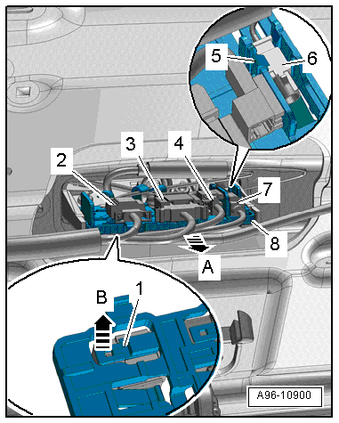
- Disconnect the connectors -2, 3 and 4- and the antenna wire -7-.
- Remove the retainer -8- in direction of -arrow A-.
- Release the tab -1- in direction of -arrow B-, slide the connector out of the mount and free up the wire.
- Push the tab -5- to the side, remove the antenna connector -6- and free up the wire.
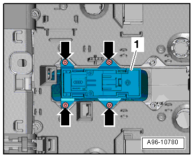
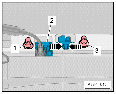
- Remove the nuts -1 and 4-.
- Disconnect the connector -3-.
- Release the tab in direction of -arrows A- and remove the button -5- toward the outside in direction of -arrow B-.
- Guide the electric wire -2- out through the opening.
Installing
Install in reverse order of removal. Note the following:
- For vehicles with a rearview camera, the Rearview Camera -R189- must be recalibrated. Refer to → Communication; Rep. Gr.91; Rearview Camera System; Rearview Camera System, Aligning and Calibrating.
Rear Lid Lock Cylinder Unlock Button -F248-, Removing and Installing, Avant
Removing
- Remove the rear lid trim panel. Refer to → Body Interior; Rep. Gr.70; Luggage Compartment Trim Panels; Lower Rear Lid Trim Panel, Removing and Installing.
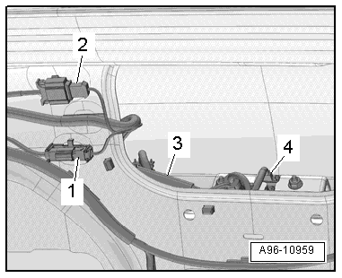
- Disconnect the connectors -2 and 4- and the antenna wire -1-.
- Free up the wiring harness -3-.
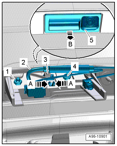
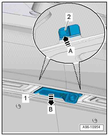
- Remove the nuts -1 and 3-.
- Release the retaining tabs in direction of -arrows-.
- Open the side tabs -2- in direction of -arrows A- and remove the button -1- toward the outside in direction of -arrow B-.
- Guide the wire through the opening.
Installing
Install in reverse order of removal. Note the following:
- For vehicles with a rearview camera, the Rearview Camera -R189- must be recalibrated. Refer to → Communication; Rep. Gr.91; Rearview Camera System; Rearview Camera System, Aligning and Calibrating.
Rear Lid Lock Button in Luggage Compartment -E406-, Removing and Installing
Rear Lid Lock Button in Luggage Compartment -E406-, Removing and Installing, Sedan
Special tools and workshop equipment required
- Wedge Set -T10383-
Depending on vehicle equipment the Locking Mechanism Button in the Rear Lid -E806- is integrated in the Rear Lid Lock Button in Luggage Compartment -E406-. If faulty the complete button unit must be replaced.
Removing
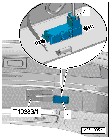
- Release the tabs in direction of -arrows- on the button -2- using Wedge Set - Wedge 1 -T10383/1-.
- Remove the button from the rear lid trim panel.
- Disconnect the connector -1-.
Installing
Install in reverse order of removal.
Rear Lid Lock Button in Luggage Compartment -E406-, Removing and Installing, Avant
Special tools and workshop equipment required
- Wedge Set -T10383-
Depending on vehicle equipment the Locking Mechanism Button in the Rear Lid -E806- is integrated in the Rear Lid Lock Button in Luggage Compartment -E406-. If faulty the complete button unit must be replaced.
Removing
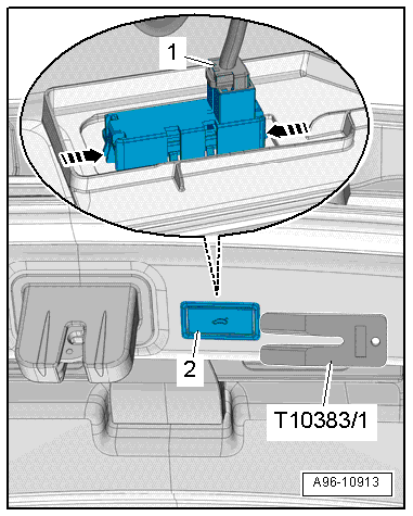
- Release the tabs in direction of -arrows- on the button -2- using Wedge Set - Wedge 1 -T10383/1-.
- Remove the button from the rear lid trim panel.
- Disconnect the connector -1-.
 Note
Note
Remove the rear lid lower trim panel if the button cannot be removed as described. Refer to → Body Interior; Rep. Gr.70; Luggage Compartment Trim Panels; Lower Rear Lid Trim Panel, Removing and Installing.
Installing
Install in reverse order of removal.
Rear Lid Warning Buzzer -H32-, Removing and Installing
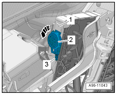
Removing
- Remove the right luggage compartment side trim panel. Refer to → Body Interior; Rep. Gr.70; Luggage Compartment Trim Panels; Luggage Compartment Side Trim Panel, Removing and Installing.
- Remove the warning buzzer -2- from the mount -1- in direction of -arrow-.
- Disconnect the connector -3-.
Installing
Install in reverse order of removal.
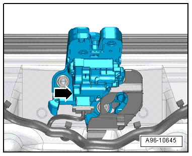
Rear Lid Contact Switch, Removing and Installing
The rear lid contact switch -arrow- is located in the rear lid lock and cannot be replaced separately if faulty.
- Replace the rear lid lock. Refer to → Body Exterior; Rep. Gr.55; Rear Lid; Hood Latch, Removing and Installing.
Driver/Front Passenger Vanity Mirror Lamp Contact Switch -F147-/-F148-, Removing and Installing
Note
The vanity mirror contact switch is located in the sun visor mount and cannot be replaced separately if faulty.
- Sun visor, removing and installing. Refer to → Body Interior; Rep. Gr.68; Equipment; Sun Visor, Removing and Installing.
Sunroof Button -E325-, Removing and Installing
Removing
- Remove the front interior/reading lamp. Refer to → Chapter "Front Interior Lamp/Reading Lamp, Removing and Installing".
- Remove the Anti-Theft Alarm System Sensor -G578-, if equipped. Refer to → Chapter "Anti-Theft Alarm System Sensor -G578-, Removing and Installing".
- Remove the bolts -arrows-.
- Remove the button -1- from the front interior/reading lamp.
Installing
Install in reverse order of removal. Note the following: