Audi A6 Typ 4G: Anti-Theft Alarm System
Overview - Interior Monitoring
Overview - Interior Monitoring, Sedan
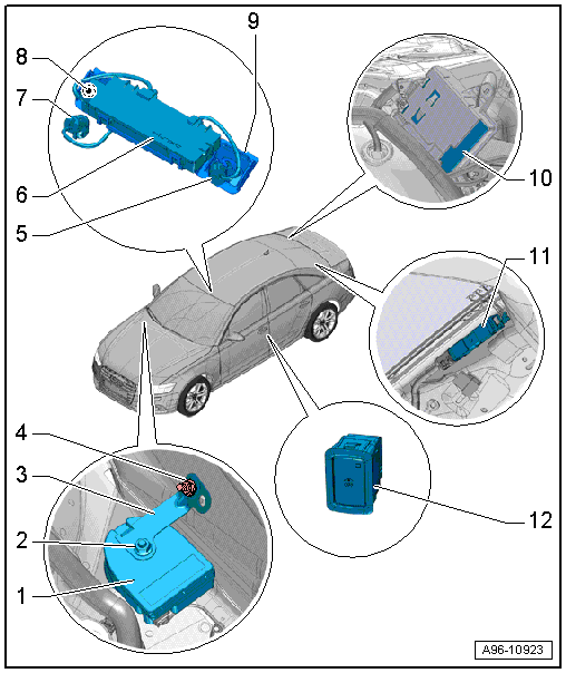
1 - Alarm Horn -H12-
- Removing and installing. Refer to → Chapter "Alarm Horn -H12-, Removing and Installing".
2 - Nut
- 3 Nm
3 - Bracket
- For Alarm Horn -H12-
4 - Nut
- 3 Nm
5 - Left Interior Monitoring Individual Sensor
- Can only be replaced together with the Anti-Theft Alarm System Sensor -G578-
6 - Anti-Theft Alarm System Sensor -G578-
- Removing and installing. Refer to → Chapter "Anti-Theft Alarm System Sensor -G578-, Removing and Installing".
7 - Individual Sensor
- For Anti-Theft Alarm System Sensor -G578-
- Removing and installing. Refer to → Chapter "Anti-Theft Alarm System Sensor -G578-, Removing and Installing".
8 - Right Interior Monitoring Individual Sensor
- Can only be changed together with the Anti-Theft Alarm System Sensor -G578-
9 - Mount
- For the Anti-Theft Alarm System Sensor -G578- and the left and right single sensors
10 - Comfort System Central Control Module -J393-
- Removing and installing. Refer to → Body Exterior; Rep. Gr.57; Central Locking; Comfort System Central Control ModuleJ393, Removing and Installing.
11 - Antenna Amplifier 2 -R111-
- With Central Locking and Anti-Theft Alarm System Antenna -R47-
- Removing and installing. Refer to → Communication; Rep. Gr.91; Antenna Systems; Antenna Amplifier, Removing and Installing.
12 - Alarm System Deactivation Switch -E217-
- Component location overview. Refer to → Chapter "Overview - Front Door Controls".
Tightening Specification for the Structure-Borne Sound Control Module Bracket
- Tighten the nuts -arrows- to 3 Nm.
Overview - Interior Monitoring, Avant
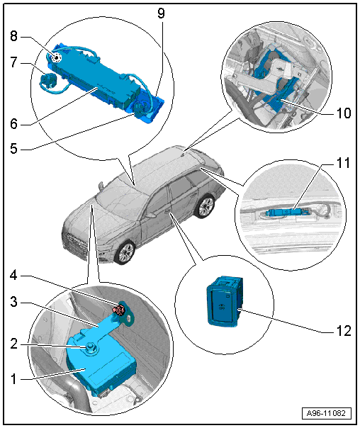
1 - Alarm Horn -H12-
- Removing and installing. Refer to → Chapter "Alarm Horn -H12-, Removing and Installing".
2 - Nut
- 3 Nm
3 - Bracket
- For Alarm Horn -H12-
4 - Nut
- 3 Nm
5 - Left Interior Monitoring Individual Sensor
- Can only be replaced together with the Anti-Theft Alarm System Sensor -G578-
6 - Anti-Theft Alarm System Sensor -G578-
- Removing and installing. Refer to → Chapter "Anti-Theft Alarm System Sensor -G578-, Removing and Installing".
7 - Individual Sensor
- For Anti-Theft Alarm System Sensor -G578-
- Removing and installing. Refer to → Chapter "Anti-Theft Alarm System Sensor -G578-, Removing and Installing".
8 - Right Interior Monitoring Individual Sensor
- Can only be changed together with the Anti-Theft Alarm System Sensor -G578-
9 - Mount
- For the Anti-Theft Alarm System Sensor -G578- and the left and right single sensors
10 - Comfort System Central Control Module -J393-
- Removing and installing. Refer to → Body Exterior; Rep. Gr.57; Central Locking; Comfort System Central Control ModuleJ393, Removing and Installing.
11 - Antenna Amplifier 2 -R111-
- With Central Locking and Anti-Theft Alarm System Antenna -R47-
- Removing and installing. Refer to → Communication; Rep. Gr.91; Antenna Systems; Antenna Amplifier, Removing and Installing.
12 - Alarm System Deactivation Switch -E217-
- Component location overview. Refer to → Chapter "Overview - Front Door Controls".
Alarm Horn -H12-, Removing and Installing
Removing
- Remove the plenum chamber cover. Refer to → Body Exterior; Rep. Gr.50; Bulkhead; Plenum Chamber Cover, Removing and Installing.
Vehicles without Structure-Borne Sound Control Module:
- Remove the nut -1-.
- Disconnect the connector -3-.
- Remove the alarm horn -2- upward.
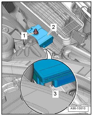
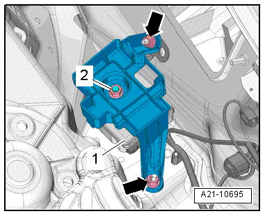
Vehicles with Structure-Borne Sound Control Module:
- Remove the structure borne sound control module. Refer to → Rep. Gr.23; Sensors.
- Remove nuts -arrows- and remove the mount.
- Remove the nut -2-.
- Disconnect the connector.
- Remove the alarm horn -1- upward.
Installing
Install in reverse order of removal.
Anti-Theft Alarm System Sensor -G578-, Removing and Installing
Removing
- Remove the front interior/reading lamp. Refer to → Chapter "Front Interior Lamp/Reading Lamp, Removing and Installing".
- Remove the single sensor -1- from the mount -2-.
- Release the tabs -arrows- and remove the mount -4- and anti-theft alarm system sensor from the interior/reading lamp -3-.
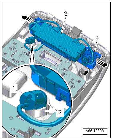
- Free up the wire -5-.
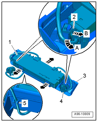
- Press the tabs to the side in direction of -arrows- and remove the anti-theft alarm system sensor -1- from the mount -3-.
- Turn the single sensors -2 and 4- counterclockwise all the way in direction of -arrow A- and remove them from the mount in direction of -arrow B-.
- Remove the anti-theft alarm system sensor.
Installing
Install in reverse order of removal.
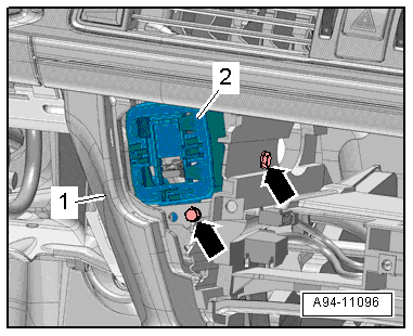
Anti-Theft Immobilizer Reader Coil, Removing and Installing
Anti-Theft Immobilizer Reader Coil -D2-, Removing and Installing
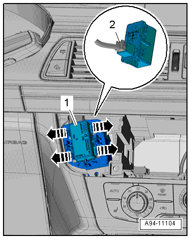
Removing
- Remove the Information Electronics Control Module 1 -J794-. Refer to → Communication; Rep. Gr.91; Infotainment System; Information Electronics Control Module 1 J794, Removing and Installing.
- Release the tabs in direction of -arrows- and remove the anti-theft immobilizer reader coil -1- from the mount.
- Disconnect the connector -2-.
Installing
Install in reverse order of removal.
Anti-Theft Immobilizer Reader Coil -D2-, Removing and Installing
Removing
- Remove the anti-theft immobilizer reading coil. Refer to → Chapter "Anti-Theft Immobilizer Reader Coil -D2-, Removing and Installing".
- Remove the driver side instrument panel cover. Refer to → Body Interior; Rep. Gr.68; Storage Compartments and Covers; Driver Side Instrument Panel Cover, Removing and Installing.
- Remove the bolts -arrows-.
- Remove the mount -2- from the instrument panel -1- downward toward the driver footwell.
Installing
Install in reverse order of removal.