Audi A6 Typ 4G: Additional Lamps and Controls Inside Passenger Compartment
Overview - Additional Lamps and Controls Inside Passenger Compartment
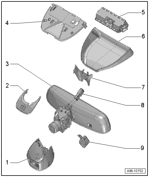
1 - Front Cover
- For the housing for the Automatic High Beam Assist Control Module -J844- with Light Recognition Sensor -G399-
2 - Upper Cover
- For Automatic High Beam Assist Control Module -J844-
3 - Interior Rearview Mirror
- Vehicles with Automatic High Beam Assist Control Module -J844- with Light Recognition Sensor -G399-
- Automatic High Beam Assist Control Module -J844- with Light Recognition Sensor -G399- integrated inside the interior rearview mirror. Cannot be replaced separately if faulty.
- Replacing the interior rearview mirror. Refer to → Body Interior; Rep. Gr.68; Interior Rearview Mirror; Interior Rearview Mirror, Removing and Installing.
4 - Retaining Plate
- Cannot be separated from the windshield
5 - Camera Control Module -J852-
- Overview. Refer to → Chapter "Overview - Driver Assistance Systems Front Camera".
6 - Lower Cover
- For Camera Control Module -J852-
7 - Rear Cover
8 - Central Connector
9 - Humidity Sensor -G355-
- There are different versions. Refer to the Parts Catalog.
- For vehicles from 03/2011 the Humidity Sensor -G355- is integrated in the Rain/Light Recognition Sensor -G397-.
Humidity sensor with part number 8K0...
- Removing and installing
Humidity sensor with part number 8U0...
- Removing and installing. Refer to → Chapter "Rain/Light Recognition Sensor, Removing and Installing".
Humidity Sensor -G355-, Removing and Installing
Humidity Sensor -G355-, Removing and Installing, without Automatic High Beam Assist
Removing
- Remove the interior rearview mirror. Refer to → Body Interior; Rep. Gr.68; Interior Rearview Mirror; Interior Rearview Mirror, Removing and Installing.
- Release the tab -2- and the tab -3- with a screwdriver in direction of -arrows-.
- Remove the rear cover -1-.
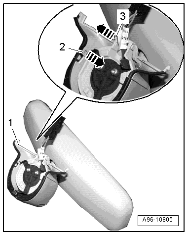
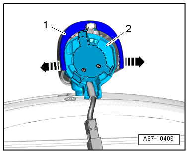
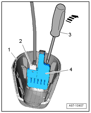
- Spread the front cover -1- apart slightly on both sides in direction of -arrows- and remove it from the interior rearview mirror base -2-.
- Disconnect the connector -2-.
- Using a small screwdriver -3-, carefully press the Humidity Sensor -G355--item 4- off the cover -1- in direction of -arrow- and remove it upward.
Installing
Install in reverse order of removal. Note the following:
- Carefully place Humidity Sensor -G355- in side guides.
 Note
Note
The cover cannot be installed if the Humidity Sensor -G355- is not inserted correctly.
Humidity Sensor -G355-, Removing and Installing, with Automatic High Beam Assist
Removing
- Remove the interior rearview mirror. Refer to → Body Interior; Rep. Gr.68; Interior Rearview Mirror; Interior Rearview Mirror, Removing and Installing.
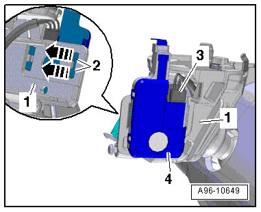
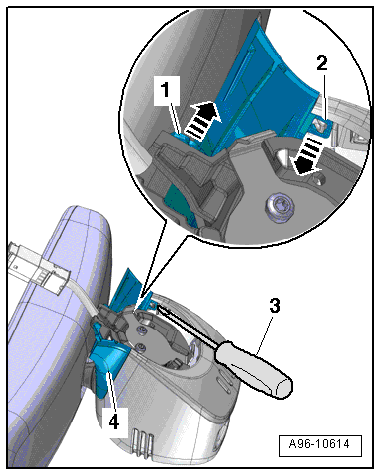
- Release the retaining tabs -1 and 2- with a screwdriver -3-.
- Disengage the rear cover -4- in direction of -arrows-.
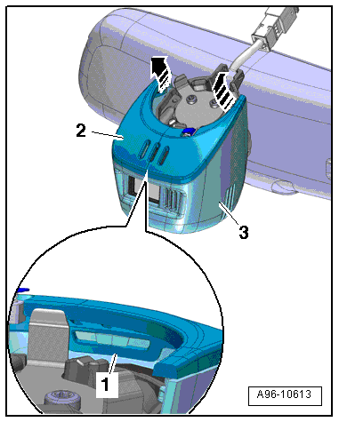
- Release the tabs in direction of -arrows- and carefully fold the upper cover -2- upward just a little.
- Disengage the retainer -1- on the front cover -3-.
- Remove the upper cover.
- Disengage the retaining hooks in the direction of the -arrow- and remove the front cover -2- downward from the guide bars -1- on the interior rearview mirror base.
- Release the retaining clips -2- in direction of -arrows- and remove the Humidity Sensor -G355--item 4- from the interior rearview mirror base -1-.
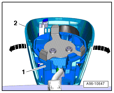
- Disconnect the connector -3-.
Installing
Install in reverse order of removal. Note the following: