Audi A6 Typ 4G: Rear Seat Backrest, Removing and Installing
Divided Rear Seat Backrest, Removing and Installing
 Note
Note
The following describes removing and installing the right 2/3 section of the backrest. Removing and installing the left 1/3 rear seat backrest is identical.
Special tools and workshop equipment required
- Trim Removal Wedge -3409-
Removing
- Remove the rear bench seat. Refer to → Chapter "Seat Bench/Single Seat, Removing and Installing".
- Vehicles with a 3-seat rear seat backrest, 2/3 right: Remove the center rear belt end fitting. Refer to → Chapter "Rear Seat Belt Latch, Removing and Installing".
Vehicles with a 3-seat rear seat backrest, 2/3 right, market-specific with a rear seat belt igniter:
 WARNING
- Follow all Safety Precautions when working with pyrotechnic components. Refer to → Chapter "Pyrotechnic Components Safety Precautions".
- Follow all regulations when disposing of pyrotechnic components. Refer to → Chapter "Airbag, Belt Tensioner and Battery Cut-Out Units, Storing, Transporting and Disposing".
- Disconnect the battery Ground (GND) cable with the ignition turned on. Refer to → Electrical Equipment; Rep. Gr.27; Battery; Battery, Disconnecting and Connecting.
WARNING
Before handling pyrotechnic components (for example, disconnecting the connector), the person handling it must "discharge static electricity". This can be done by touching the door striker, for example.
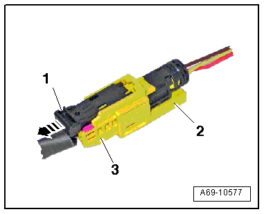
- Disconnect the connector.
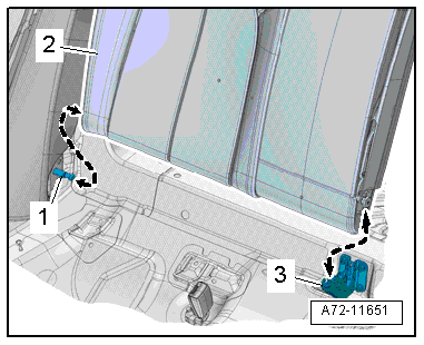
- Pull the locking mechanism -1- in direction of -arrow- and disconnect the electrical connectors -2- and -3-.
Vehicles with Backrest Release:
- Open coupling rod cover -1-.
- Unclip the release cable -4- at the coupling rod -2- for the release cable -arrow-.
- Remove the release cable nipple -3-.
Continuation for All Vehicles
- Fold the rear seat backrest forward.
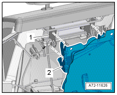
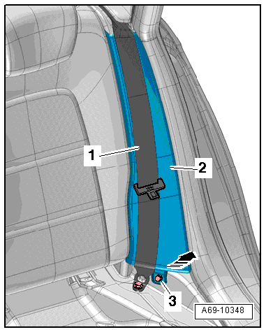
- Remove the securing bracket bolt -2-.
- If the vehicle has a pass-through door, open the door and remove the securing bracket -1- from the center support -arrow-.
Note
The cushion and cover are not shown in the illustration.
- Lift the rear seat backrest -2- out of the center support -3- and pull it out toward the center of the vehicle out of its outer mounts -1--arrows-.
- Remove rear seat backrest from the vehicle.
Installing
Install in reverse order of removal. Note the following:
Right rear seat backrest 2/3, country-specific with rear seat belt igniter:
WARNING
- Follow all Safety Precautions when working with pyrotechnic components. Refer to → Chapter "Pyrotechnic Components Safety Precautions".
- Before handling pyrotechnic components (for example, connecting the connector), the person handling it must "discharge static electricity". This can be done by touching the door striker, for example.
Note
- Make sure the connectors are installed correctly and are secure.
- Make sure the wires do not get caught.
WARNING
Ignition must be on when connecting battery. If pyrotechnic components (for example, airbag, belt tensioner) are not repaired correctly, they may deploy unintentionally after connecting battery. There must not be anyone inside the vehicle when connecting the battery.
DANGER!
When working on vehicles with the ignition already switched on or that are ready to drive there is a danger of the engine starting unexpectedly and of being poisoned by gas in enclosed areas. Risk of body parts and/or clothing being clamped or pulled.
Perform the following before switching on the ignition:
- Move the selector lever into P.
- Activate the parking brake
- Turn off the ignition.
- Open the hood
- Connect the charger, such as the Battery Charger -VAS5095A- to the jump start of the 12V vehicle electrical system.
- Turn on the ignition.
- Connect the battery ground cable with the ignition turned on. Refer to → Electrical Equipment; Rep. Gr.27; Battery; Battery, Disconnecting and Connecting.
Installation notes, for example tightening specifications, replacing components. Refer to → Chapter "Overview - Rear Seat Backrest".
Rear Seat Backrest, Fixed, Removing and Installing
Removing
- Remove the rear bench seat. Refer to → Chapter "Seat Bench/Single Seat, Removing and Installing".
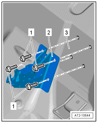
- In the luggage compartment, remove the screw for the rear seat seatback -1-.
- Remove the bolts -3-.
- Vehicles equipped with backrest heating: disconnect the backrest heating harness connector.
- Pull the top part of the rear seat seatback from its mounts -2-.
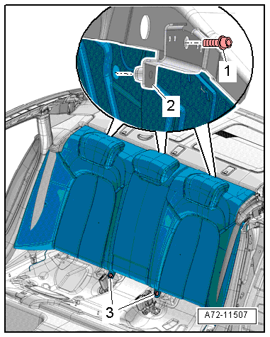
- Detach the rear seat seatback -1- moving it sideways and out of the retaining pins -2-; then remove it from the vehicle.
Installing
Install in reverse order of removal. Note the following:
Installation notes, for example tightening specifications, replacing components. Refer to → Chapter "Overview - Rear Seat Backrest, Standard Seat/Sport Seat".
Rear Seat Backrest, Removing and Installing, Multi-contour Seat
Removing
WARNING
- Follow all Safety Precautions when working with pyrotechnic components. Refer to → Chapter "Pyrotechnic Components Safety Precautions".
- Follow the additional safety precautions when working with the side airbag. Refer to → Chapter "Side Airbag Additional Safety Precautions".
- Disconnect the battery Ground (GND) cable with the ignition turned on. Refer to → Electrical Equipment; Rep. Gr.27; Battery; Battery, Disconnecting and Connecting.
- Remove the rear bench seat. Refer to → Chapter "Seat Bench/Single Seat, Removing and Installing".
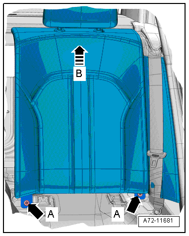
- Remove the bolts -arrows A- for the rear seat backrest.
- Press the rear seat backrest upward -arrow B-.
- Remove the rear backrest frames -1- at the retaining bracket -2- from the rear panel.
- Pull the rear seat backrest as far forward as possible.
WARNING
Before handling pyrotechnic components (for example, disconnecting the connector), the person handling it must "discharge static electricity". This can be done by touching the door striker, for example.
- Disconnect the connector (yellow) from the rear side airbag.
- Pull the locking mechanism -1- in direction of -arrow- and disconnect the electrical connectors -2 and 3-.
- Connect Airbag Lockout Adapter -VAS6282- to the side airbag harness connector. Refer to → Chapter "Airbag Adapter, Connecting and Disconnecting".
- Disconnect the connector and remove the rear seat backrest from the vehicle.
Installing
- Install rear seat backrest in the vehicle and engage backrest frame -1- on the retaining bracket -2-.
Installation is performed in reverse order of removal, while noting the following:
WARNING
- Follow all Safety Precautions when working with pyrotechnic components. Refer to → Chapter "Pyrotechnic Components Safety Precautions".
- Before handling pyrotechnic components (for example, connecting the connector), the person handling it must "discharge static electricity". This can be done by touching the door striker, for example.
Note
Make sure the connectors are installed correctly and are secure.
WARNING
Ignition must be on when connecting battery. If pyrotechnic components (for example, airbag, belt tensioner) are not repaired correctly, they may deploy unintentionally after connecting battery. There must not be anyone inside the vehicle when connecting the battery.
- Connect the battery Ground (GND) cable with the ignition turned on. Refer to → Electrical Equipment; Rep. Gr.27; Battery; Battery, Disconnecting and Connecting.
Note
If the Airbag Indicator Lamp -K75- indicates a fault, check the Diagnostic Trouble Code (DTC) memory, erase it and check it again. Refer to Vehicle Diagnostic Tester.
Installation notes, for example tightening specifications, replacing components. Refer to → Chapter "Overview - Rear Seat Backrest, Multi-contour Seat".
Mount/Sleeve/Pins, Removing and Installing, Rear Seat Backrest
Special tools and workshop equipment required
- Trim Removal Wedge -3409-
Removing
- Remove the rear seat backrest. Refer to → Chapter "Rear Seat Backrest, Removing and Installing".
Removing Center Support
Note
The rear seat backrest only needs to be disengaged from the mounts to remove and install the center bracket.
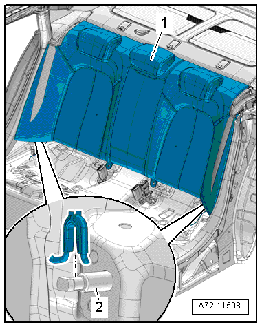
- Remove the bolts -1-.
- Remove the center support -2- from the floor panel -3-.
Remove Inner Mounting Pin
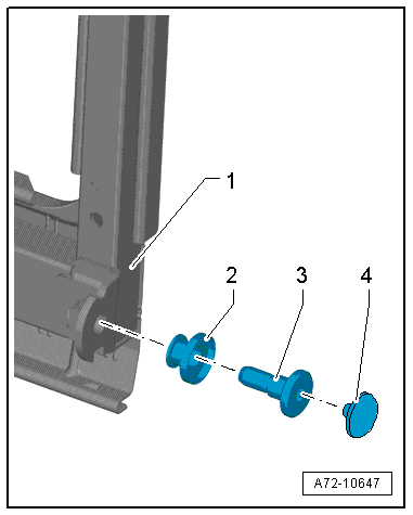
- Remove the chafe protection -4- and then remove the mounting pin -3- from the rear seat backrest frame -1-.
Note
The cushion and cover are not shown in the illustration.
- Remove the bearing sleeve -2- from the mounting pin.
Remove Exterior Bearing Sleeve
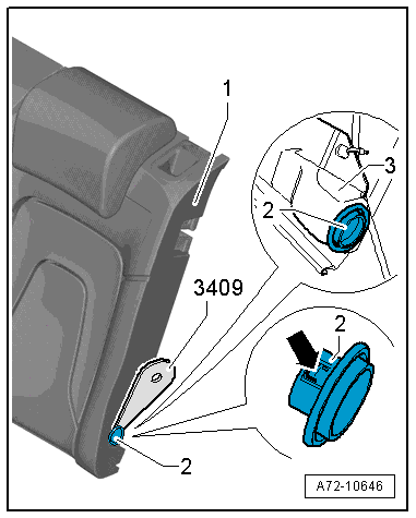
- Unclip the bearing sleeve -2- from the rear seat backrest frame -1- using the Trim Removal Wedge -3409- and remove it.
 Caution
Be careful not to damage the backrest cover when removing the bearing sleeve.
Installing
Install in reverse order of removal. Note the following:
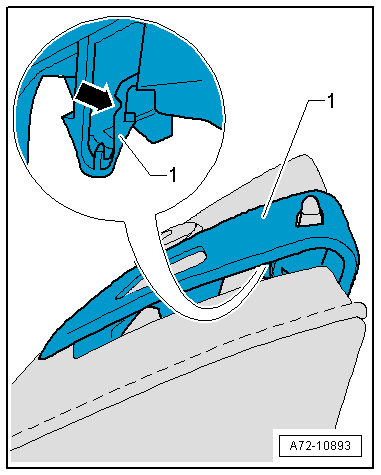
- Make sure all tabs -arrow- engage completely in the mount -3- on the rear seat backrest -1-.
Installation notes, for example tightening specifications, replacing components. Refer to → Chapter "Overview - Rear Seat Backrest".
Side Cushion, Removing and Installing
Removing
- Remove the rear bench seat. Refer to → Chapter "Seat Bench/Single Seat, Removing and Installing".
With Rear Side Airbag
WARNING
- Follow all Safety Precautions when working with pyrotechnic components. Refer to → Chapter "Pyrotechnic Components Safety Precautions".
- Follow the additional safety precautions when working with the side airbag. Refer to → Chapter "Side Airbag Additional Safety Precautions".
- Follow all regulations when disposing of pyrotechnic components. Refer to → Chapter "Airbag, Belt Tensioner and Battery Cut-Out Units, Storing, Transporting and Disposing".
- Disconnect the battery Ground (GND) cable with the ignition turned on. Refer to → Electrical Equipment; Rep. Gr.27; Battery; Battery, Disconnecting and Connecting.
Continuation for All Equipment Levels
- Remove the bolt -3-.
- Fold the rear seat backrest forward.
- Hold the seat belt webbing -1- to the side and remove the lower part of the side cushion -2- forward -arrow-.
- Pull the side cushion downward and remove it from the belt guide.
With Rear Side Airbag
WARNING
Before handling pyrotechnic components (for example, disconnecting the connector), the person handling it must "discharge static electricity". This can be done by touching the door striker, for example.
- Disconnect the connector (yellow) from the rear side airbag.
- Pull the locking mechanism -1- in direction of -arrow- and disconnect the electrical connectors -2 and 3-.
- Connect airbag adapter connector Airbag Lockout Adapter -VAS6282- to the side airbag harness connector. Refer to → Chapter "Airbag Adapter, Connecting and Disconnecting".
Installing
Install in reverse order of removal. Note the following:
With Rear Side Airbag
WARNING
- Follow all Safety Precautions when working with pyrotechnic components. Refer to → Chapter "Pyrotechnic Components Safety Precautions".
- Before handling pyrotechnic components (for example, connecting the connector), the person handling it must "discharge static electricity". This can be done by touching the door striker, for example.
Note
Make sure the connectors are installed correctly and are secure.
WARNING
Ignition must be on when connecting battery. If pyrotechnic components (for example, airbag, belt tensioner) are not repaired correctly, they may deploy unintentionally after connecting battery. There must not be anyone inside the vehicle when connecting the battery.
DANGER!
When working on vehicles with the ignition already switched on or that are ready to drive there is a danger of the engine starting unexpectedly and of being poisoned by gas in enclosed areas. Risk of body parts and/or clothing being clamped or pulled.
Perform the following before switching on the ignition:
- Move the selector lever into P.
- Activate the parking brake
- Turn off the ignition.
- Open the hood
- Connect the charger, such as the Battery Charger -VAS5095A- to the jump start of the 12V vehicle electrical system.
- Turn on the ignition.
- Connect the battery GND cable with the ignition turned on. Refer to → Electrical Equipment; Rep. Gr.27; Battery; Battery, Disconnecting and Connecting.
Note
If the Airbag Indicator Lamp -K75- indicates a fault, check the Diagnostic Trouble Code (DTC) memory, erase it and check it again. Refer to Vehicle Diagnostic Tester.
Information for installation: for example, tightening specifications, replacing body parts. Refer to → Chapter "Overview - Rear Seat Backrest" and → Chapter "Overview - Rear Side Airbag".
Seat Adjustment Control Module, Removing and Installing, Multi-contour Seat
Removing
WARNING
- Follow all Safety Precautions when working with pyrotechnic components. Refer to → Chapter "Pyrotechnic Components Safety Precautions".
- Before handling pyrotechnic components (for example, disconnecting the connector), the person handling it must "discharge static electricity". This can be done by touching the door striker, for example.
- Remove the Multi-contour seat. Refer to → Chapter "Rear Seat Backrest, Removing and Installing, Multi-contour Seat".
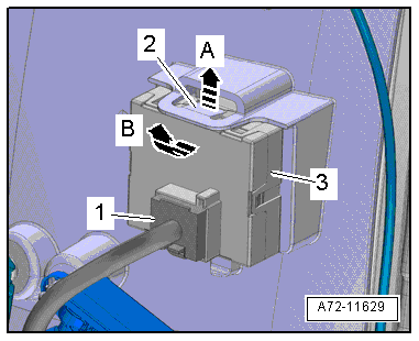
- Disconnect the connector -1- from the control module.
- Carefully unclip the control module from the tabs with a screwdriver-2--arrow A-.
- Remove the control module -3- towards the rear -arrow B-, disengage the hooks from the mount, and remove the control module upwards.
Installing
WARNING
- Follow all Safety Precautions when working with pyrotechnic components. Refer to → Chapter "Pyrotechnic Components Safety Precautions".
- Before handling pyrotechnic components (for example, connecting the connector), the person handling it must "discharge static electricity". This can be done by touching the door striker, for example.
- Observe all measures when installing the Multi-contour seat. Refer to → Chapter "Rear Seat Backrest, Removing and Installing, Multi-contour Seat".
Install in reverse order of removal. Note the following:
Installation notes, for example tightening specifications, replacing components. Refer to → Chapter "Component Location Overview - Electric and Electronic Components".
Rear Seat Backrest Rear Panel/Mount, Removing and Installing, Multi-contour Seat
Special tools and workshop equipment required
- Pop Rivet Pliers -VAG1753B-
- Drill
- Protective eyewear
Removing
WARNING
- Follow all Safety Precautions when working with pyrotechnic components. Refer to → Chapter "Pyrotechnic Components Safety Precautions".
- Before handling pyrotechnic components (for example, connecting the connector), the person handling it must "discharge static electricity". This can be done by touching the door striker, for example.
- Remove the Multi-contour seat. Refer to → Chapter "Rear Seat Backrest, Removing and Installing, Multi-contour Seat".
- Remove the rear center armrest trim mount. Refer to → Chapter "Center Armrest, Removing and Installing, Market-Specific".
Note
Lay plastic film to protect against the metal shavings.
WARNING
Risk of injury!
Wear protective eyewear.
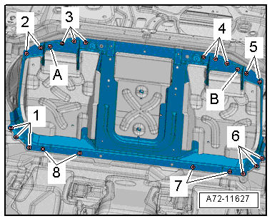
- Drill out rivets -1 through 8-.
- Remove the bolts -A and B- and remove the rear panel.
Installing
- Install the rear panel in the vehicle and align the openings with rivets and rivet them.
WARNING
- Follow all Safety Precautions when working with pyrotechnic components. Refer to → Chapter "Pyrotechnic Components Safety Precautions".
- Before handling pyrotechnic components (for example, connecting the connector), the person handling it must "discharge static electricity". This can be done by touching the door striker, for example.
- Observe all measures when installing the backrest. Refer to → Chapter "Rear Seat Backrest, Removing and Installing".
Install in reverse order of removal.
Installation notes, for example tightening specifications, replacing components. Refer to → Chapter "Overview - Rear Seat Backrest, Multi-contour Seat".
Rear Seat Backrest Fan, Removing and Installing
Removing
WARNING
- Follow all Safety Precautions when working with pyrotechnic components. Refer to → Chapter "Pyrotechnic Components Safety Precautions".
- Before handling pyrotechnic components (for example, disconnecting the connector), the person handling it must "discharge static electricity". This can be done by touching the door striker, for example.
- Remove the Multi-contour seat. Refer to → Chapter "Rear Seat Backrest, Removing and Installing, Multi-contour Seat".
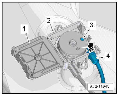
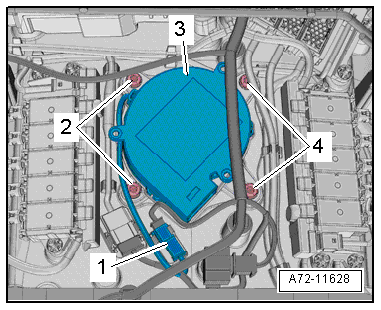
- Disconnect the connectors -1- and free them up.
- Remove the bolts -2 and 4- for the fan.
- Remove the fan -3-.
Installing
WARNING
- Follow all Safety Precautions when working with pyrotechnic components. Refer to → Chapter "Pyrotechnic Components Safety Precautions".
- Before handling pyrotechnic components (for example, connecting the connector), the person handling it must "discharge static electricity". This can be done by touching the door striker, for example.
- Observe all measures when installing the Multi-contour seat. Refer to → Chapter "Rear Seat Backrest, Removing and Installing, Multi-contour Seat".
Install in reverse order of removal. Note the following:
Installation notes, for example tightening specifications, replacing components. Refer to → Chapter "Overview - Seat Bench Fan/Single Seat, Multi-contour Seat".
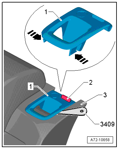
Locking Mechanism Trim, Removing and Installing
Special tools and workshop equipment required
- Trim Removal Wedge -3409-
Removing
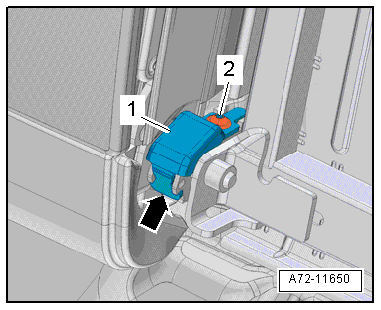
- Unlock the rear seat backrest.
- Make sure the button -2- (indicator) is in the "up" position.
- Push the tabs -arrows- on both sides of the trim using a Trim Removal Wedge -3409-.
- Remove the trim -1- upward and off the rear seat backrest -3-.
- Remove the trim -1- as far as possible upward from the rear seat backrest.
- Pry the catch -arrow- out of the locking mechanism using a flat blade screwdriver.
- Remove the trim upward from the rear seat backrest.
Note
The catch on the predetermined breaking point -arrow- must be destroyed after removing the trim and lock cylinder.
Installing
Install in reverse order of removal. Note the following:
- Make sure the button moves easily after installing the trim.
- When installing the trim -1-, make sure the lock cylinder installation position is correct.
Installation notes, for example tightening specifications, replacing components. Refer to → Chapter "Overview - Locking Mechanism, Sedan".