Audi A6 Typ 4G: Upper Control Arm, Removing and Installing
Special tools and workshop equipment required
- Torque Wrench 1331 5-50Nm -VAG1331-
- Torque Wrench 1331 Insert - Ring Wrench - 16mm -VAG1331/12-
- Torque Wrench 1332 40-200Nm -VAG1332-
- Engine and Gearbox Jack -VAS6931-
- Engine/Gearbox Jack Adapter - Wheel Hub Support -T10149-
- For a vehicle with air suspension Vehicle Diagnostic Tester
Removing
- Place the vehicle on a hoist. Refer to → Chapter "Raising and Lowering with Open and Closed Air Suspension System".
- Remove the tower brace. Refer to → Chapter "Tower Brace, Removing and Installing".
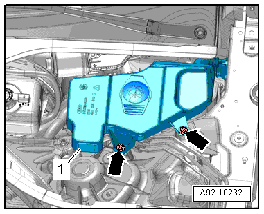
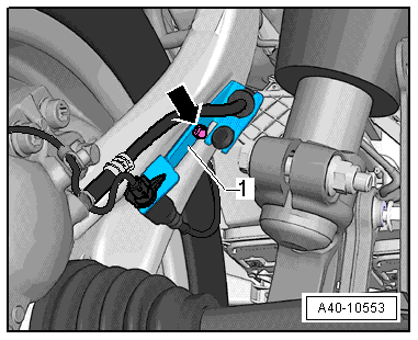
- Remove the bolts -arrows- and move the windshield washer fluid reservoir -1- slightly to the side.
- Remove the wheel. Refer to → Chapter "Wheels and Tires".
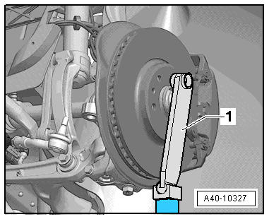
- Secure the brake disc with a wheel bolt.
- Remove the bolt -1-.
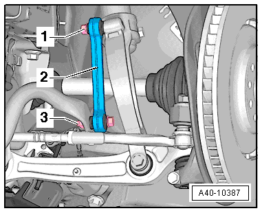
- Remove the bolt -3-.
- Remove the brake line and wires from the bracket on the wheel bearing housing.
- Turn the wheel hub until one of the holes for the wheel bolts is on top.
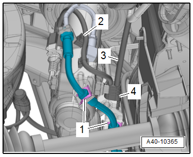
Applies to Audi RS6
- Free up the Dynamic Ride Control (DRC) system hose by removing the retaining clips -1-.
- Free up the brake hose -3- and the electrical wires -2 and 4-.
Applies to All
- Install the Engine/Gearbox Jack Adapter - Wheel Hub Support -T10149--1- with wheel bolt on wheel hub.
- Support the wheel bearing housing over the Engine/Gearbox Jack Adapter - Wheel Hub Support -T10149- using the Engine and Gearbox Jack -VAS6931-.
 WARNING
- Do not lift or lower the vehicle when the Engine and Gearbox Jack -VAS6931- is below the vehicle.
- Do not leave the Engine and Gearbox Jack -VAS6931- under the vehicle any longer than necessary.
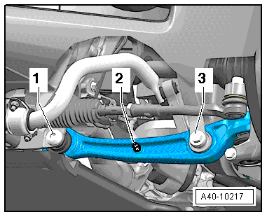
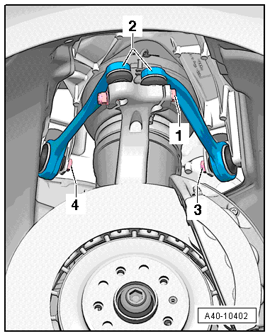
- Disconnect the threaded connection -1-.
 Note
Note
The slits in the wheel bearing housing must not be widened using a chisel or similar tool!
- Remove booth joint pins in the upper control arm -2- from the wheel bearing housing.
Note
Do not lower wheel bearing housing more than necessary.
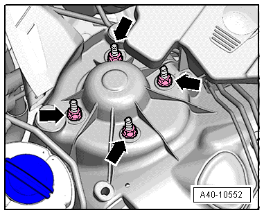
- Remove the nuts -arrows- and swivel the air/steel spring shock absorber downward and out of the suspension strut tower.
- The air/steel spring shock absorber remains inside the vehicle.
Note
Be careful not to damage any components.
- Remove the bolts -4 and 3- and remove the front upper control arm and the rear upper control arm.
Installing
Install in reverse order of removal. Note the following:
Note
Bonded rubber bushings have a limited range of motion. Only tighten suspension bolts when vehicle is in curb weight or control position. Refer to → Chapter "Wheel Bearing in Control Position, Lifting Vehicles with Air Suspension" or → Chapter "Wheel Bearing in Curb Weight, Lifting Vehicles with Coil Spring".
- Install the upper control arm -2- and tighten the bolt -4 and 3- hand-tight.
- Insert both of upper control arm joint pins -2- in the wheel bearing housing and insert the bolt -1-.
- Install the air/steel spring shock absorber into the suspension strut tower and tighten the nuts -arrows- diagonally.
- Install the bolting -3- but do not tighten it.
- Tighten the bolting -1-.
Note
Push the upper control arms down as far as possible while tightening the bolts!
- Lift the wheel bearing into the control position. Refer to → Chapter "Wheel Bearing in Control Position, Lifting Vehicles with Air Suspension" or → Chapter "Wheel Bearing in Curb Weight, Lifting Vehicles with Coil Spring".
Note
Push the upper control arm toward the inside of the vehicle when tighten the bolt -3 or 4-.
- Tighten the bolt -4 or 3-.
- Tighten the rest of the bolting.
- Install the wheel. Refer to → Chapter "Wheels and Tires".
- Place vehicle on wheels. Refer to → Chapter "Raising and Lowering with Open and Closed Air Suspension System".
- To determine if an axle alignment is required, see Table. Refer to → Chapter "Evaluating Need for Axle Alignment".
Upper Control Arm Bearing, Replacing
Special tools and workshop equipment required
- Subframe Bushing Tool Kit -3301-
- Bearing Installer - Multiple Use -3348-
Procedure
- The upper control arm us removed. Refer to → Chapter "Upper Control Arm, Removing and Installing"
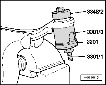
Pull Out Bonded Rubber Bushing
Note
Control arms must only be clamped in a vise with protective vise jaw lining!
- Order the special tools as illustrated.
- Turn the nut and remove the bonded rubber bushing.
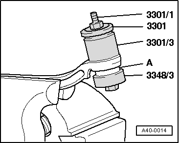
Pulling In Bonded Rubber Bushing
Note
Do not use lubricant!
A = bearing
- Order the special tools as illustrated.
- Install the bonded rubber bushing all the way.
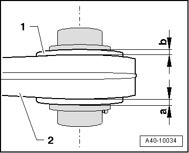
- Check the press-in depth for the bonded rubber bushing -1- inside the control arm -2-.
- Dimensions -a and b- must be identical.
- Adjust the bonded rubber bushing if the dimensions -a and b- are different.
- Install the upper control arm. Refer to → Chapter "Upper Control Arm, Removing and Installing".