Audi A6 Typ 4G: Refrigerant Circuit, Discharging with Service Station
- Work procedure may vary depending on the type of tools selected (the tool-specific operating instructions should therefore be followed).
- The refrigerant circuit is to be discharged if parts of the refrigerant circuit are to be removed, if there is any doubt about the quantity of refrigerant in the circuit or if safety precautions so require.
- All the necessary usage information for working with the refrigerant service station can be found in the service station operating instructions.
Draining:
- Turn off the ignition.
- Connect service station in line with operating instructions to vehicle service connections. Refer to vehicle-specific refrigerant circuit. Start up service station. Refer to → Heating, Ventilation and Air Conditioning; Rep. Gr.87; System Overview - Refrigerant Circuit or (vehicle-specific repair manual).
Additionally on vehicles with an electric operated valves in the refrigerant circuit, which cannot be opened without power (for example the Audi Q7 e-tron):
 Note
Note
On vehicles with high-voltage system and additional functions of the A/C system ("heat pump operation" or "cooling the high-voltage battery") valves may be installed in the refrigerant circuit which cannot be opened without power. These valves are opened and closed for example via a step motor and after switching off the ignition are no longer activated. To completely drain, correctly discharge and charge the refrigerant circuit no areas may be closed, for this reason the valves must be opened before these procedures. Refer to → Heating, Ventilation and Air Conditioning; Rep. Gr.87; Refrigerant Circuit; System Overview - Refrigerant Circuit and the Vehicle Diagnostic Tester in the "Guided Fault Finding" function.
- Open the electrically activated valves, which to now open without power using the Vehicle Diagnostic Tester in the "Guided Fault Finding" function.
All
- Discharge the refrigerant circuit using the A/C service station according to the operating instructions.
 Caution
There is a risk of damaging the A/C compressor if the refrigerant circuit is empty.
Do not start the motor if the refrigerant circuit is empty.
- Depending on the version of the A/C Service Station, the pressure of the refrigerant circuit may be less than 1 bar (14.5 psi) absolute pressure after it has been discharged.
- Depending on the version of the A/C compressor, it may be damaged if the pressure in the refrigerant circuit is too low.
- Do not start the engine while the refrigerant circuit pressure is less than the ambient pressure.
 WARNING
There is a danger of ice-up.
Refrigerant may leak out if refrigerant circuit is not discharged.
Refrigerant must be extracted before opening refrigerant circuit. If refrigerant circuit is not opened within 10 minutes of extraction, pressure may form in refrigerant circuit due to evaporation. Extract the refrigerant once more.
Note
- There is a possibility of refrigerant oil being extracted from the refrigerant circuit together with the refrigerant. To ensure compressor lubrication, the refrigerant oil in the circuit must be topped up with fresh oil. Refer to → Chapter "Refrigerant R134a Capacities, Refrigerant Oil and Approved Refrigerant Oils".
- On vehicles fitted with a compressor with no A/C clutch (with A/C Compressor Regulator Valve -N280-) the engine should not be run for longer than absolutely necessary with the refrigerant circuit empty (A/C compressor always in operation as well).
- On vehicles with a compressor with no A/C clutch, the engine is only to be started following complete assembly of the refrigerant circuit (avoid high engine speeds).
- Depending on the A/C compressor version, there may be a valve installed on the high pressure side of the A/C compressor, which prevents the liquid refrigerant from flowing back into the compressor once the A/C is turned off. If an A/C compressor with this valve is installed in a vehicle with a refrigerant circuit having an expansion valve, then it may take some time until the pressure in the high pressure side decreases (the expansion is cold and the pressure in the low pressure side quickly increases after it is turned off, the expansion valve closes and the refrigerant flows slowly into the low pressure side). If the A/C compressor is switched on (or the refrigerant circuit is evacuated on the low pressure side) the pressure on the low pressure side goes down, the expansion valve open and the refrigerant can flow of the low pressure side.
- Depending on the version of the A/C service station, the previous operating conditions and the ambient temperatures, etc., the amount displayed by the A/C service station for the evacuated refrigerant R134a can vary from the actual evacuated amount. The amount displayed by the A/C service station for the evacuated refrigerant is therefore only a reference point of the amount of refrigerant actually evacuated from the refrigerant circuit. Also pay attention to the A/C service station operating instructions and technical product description.
Should work be performed on the vehicle after discharging which does not require using the A/C service station
- Disconnect the A/C service station from the refrigerant circuit and turn it off.
Should the refrigerant circuit after the discharge be evacuated and refilled. Refer to → Chapter "Refrigerant Circuit, Charging with Service Station".
Refrigerant Circuit, Discharging with Service Station
- The work procedure is always to be performed as described in the operating instructions for the A/C service station.
- The quantity of refrigerant oil in the circuit is checked and if necessary corrected. Refer to → Chapter "Refrigerant R134a Capacities, Refrigerant Oil and Approved Refrigerant Oils".
- The quantity of refrigerant in the service station is checked.
The refrigerant circuit must be evacuated before it is filled with refrigerant (vacuum). Moisture is also extracted from the circuit.
Leaks may be found when evacuating the refrigerant circuit.
Evacuating:
Caution
- Do not start the engine during the evacuation process or when there is a vacuum in the refrigerant circuit.
- The A/C compressor could be damaged if the engine is started when there is a vacuum in the refrigerant circuit.
- Only start the engine when the refrigerant circuit is filled.
- Turn off the ignition.
- Connect the service station to the power supply.
- Connect charging hose of service station to vehicles refrigerant circuit with quick-release coupling adapter. Refer to vehicle-specific refrigerant circuit. Refer to → Heating, Ventilation and Air Conditioning; Rep. Gr.87; System Overview - Refrigerant Circuit (vehicle-specific repair manual).
- Only tighten the handwheel on the quick-release coupling adapter just enough so the valves in the service connections are securely open. Do not put too much pressure on the valve.
Note
If pressure is to be measured after charging system on vehicles with a service connection on one side of the refrigerant circuit only, use valve adapter and charging hose with valve opener. Refer to → Chapter "A/C Service Station, Connecting".
Additionally on vehicles with an electric operated valves in the refrigerant circuit, which cannot be opened without power (for example the Audi Q7 e-tron):
Note
- On vehicles with high-voltage system and additional functions of the A/C system ("heat pump operation" or "cooling the high-voltage battery") valves may be installed in the refrigerant circuit which cannot be opened without power. These valves are opened and closed for example via a step motor and after switching off the ignition are no longer activated. To completely drain, correctly discharge and charge the refrigerant circuit no areas may be closed, for this reason the valves must be opened before these procedures. Refer to → Heating, Ventilation and Air Conditioning; Rep. Gr.87; Refrigerant Circuit; System Overview - Refrigerant Circuit and use the Vehicle Diagnostic Tester in the "Guided Fault Finding" function.
- The check valves in the refrigerant circuit in the flow direction have a specified residual pressure (approximately 0.1 bar or 100 mbar). So that the refrigerant circuit can be completely evacuates (residual pressure less than 5 mbar) all electrically activated valves must be opened.
- Open the electrically activated valves, which to now open without power using the Vehicle Diagnostic Tester in the "Guided Fault Finding" function.
All
- Turn on the service station and evacuate the refrigerant circuit for at least 30 minutes. The pressure reading must indicate an absolute pressure of less than 10 bar (145 psi) (corresponding to 990 mbar (14.36 psi) vacuum).
Note
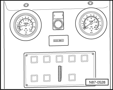
At this pressure, both green Light Emitting Diodes (LED) light up, for example, on the current service station. Refer to the Parts Catalog (Tools; Special Tools and Equipment: A/C and Heating).
- Turn off the service station and allow it to stand for at least one hour.
- If the vacuum display (LED chain) does not change, the system is free of leaks and can be charged.
Note
- A current vacuum reading (LED) is only obtained using the current service station, for example (for currently available service stations. Refer to the Parts Catalog (Tools; Special Tools and Equipment: A/C and Heating) after pressing the Evacuate button again.
- If with this service station the upper (green) LEDs do not light immediately after turning on, either the refrigerant circuit is leaking or there is still residual moisture/refrigerant in the circuit.
If the vacuum is not maintained or cannot generate a sufficient vacuum, perform the following:
- If the pressure in refrigerant circuit increases slowly after evacuating, for example, through evaporation:
- If it is possible that the refrigerant circuit may have leaks, evacuate and check the vacuum display again over several hours Only when the vacuum is maintained can the refrigerant circuit be charged.
- If the refrigerant circuit is sealed, it can be filled.
- If there is a leak that allowed enough air to enter during evacuation that the A/C service station cannot generate a sufficient vacuum or that the vacuum is lost immediately after switching the A/C service station off:
- Determine the location of the leak in the refrigerant circuit as follows:
Note
- A large leak can be identified if a maximum of pressure of 15 bar (217 psi) can be generated in the refrigerant circuit using clean, dry compressed air or nitrogen. Refer to → Chapter "Refrigerant Circuit, Flushing with Compressed Air and Nitrogen". If the leak is large enough, the sound of escaping air or gas can be heard at the location of the leak.
- Add the compressed air or nitrogen to the closed refrigerant circuit through the service connection after fitting it with a quick-release connector adapter.
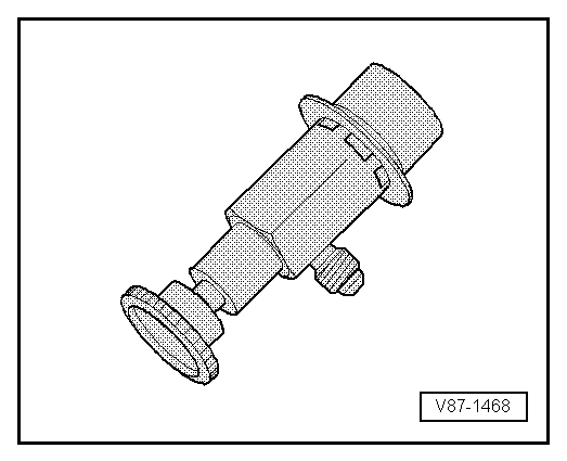
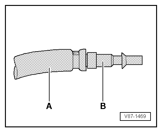
- The quick-release coupling adapter for service connections can be connected to the air compressor using a modified filler hose -A- (for example, with 5/8" 18 UNF threads, different from the threads on the quick-release coupling adapter) and a suitable adapter -B-. Refer to → Chapter "Improvised Tools". This keeps humidity, oil and dirt coming out of the workshop compressed air system from getting into the A/C refrigerant circuit. Also use a combination fine-gauge filter for compressed air systems such as those that are standard in paint shops. Install it between the compressed air system and the filler hose -A-. Refer to the Parts Catalog (Tools; Special Tools and Equipment: A/C and Heating).
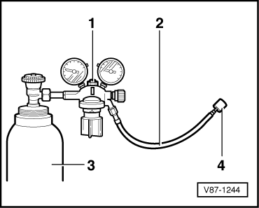
- A compressed gas cylinder filled with nitrogen -3- can be connected to the closed refrigerant circuit using a pressure gauge battery with a pressure reducer for nitrogen (maximum reduction pressure: 15 bar (217 psi) ) -1- and a filler hose -2- (for example, with 5/8" 18 UNF threads) connected to the service connection. A quick-release coupling adapter must also be connected to the service connection. Refer to → Chapter "Commercially Available Tools and Materials".
- Slowly increase the pressure in the refrigerant circuit to a maximum of 15 bar (217 psi).
WARNING
- Nitrogen can leak uncontrolled from the cylinder.
- Make exclusive use of pressure reducers for nitrogen cylinders (maximum work pressure 15 bar (217 psi) ).
- When testing for leaks with nitrogen (maximum permissible pressure 15 bar (217 psi) ), always work with a pressure reducer for nitrogen bottles.
- Use appropriate extraction units to draw off gas mixture escaping from components.
- Find the location of the leak by listening for the sound of venting gas.
- Repair the leak.
- Evacuate and again observe the vacuum display over a period of hours. Only when the vacuum is maintained can the refrigerant circuit be charged.
- If there is a leak that is small enough that no air or very little air vents through it and the A/C service station can generate a sufficient vacuum: The vacuum indicator does not increase after switching the A/C system service station or only increases slowly, indicating that air is only entering through a small leak.
- Add 100 grams of refrigerant to the circuit, find the location of the leak using an electronic leak detector and repair it. Refer to → Chapter "Refrigerant Circuit, Tracing Leaks Using Electronic Leak Detector") or add UV contrast dye to the refrigerant and find the location of the leak with the Leak Detection Kit -VAS6201A-and repair it. Refer to → Chapter "Leak Detection on Refrigerant Circuit Using Leak Detection Kit -VAS6201A-".
- Empty the refrigerant circuit, if necessary. Refer to → Chapter "Refrigerant Circuit, Discharging with Service Station".
- Evacuate and check the vacuum display again over several hours. Only when the vacuum is maintained can the refrigerant circuit be charged.
Refrigerant Circuit, Charging with Service Station
Note
The entire refrigerant charge can be added to either the high or low pressure side. Refer to → Chapter "Refrigerant R134a Capacities, Refrigerant Oil and Approved Refrigerant Oils".
- The work procedure is always to be performed as described in the operating instructions for the A/C service station.
- Before pouring in refrigerant, correct the quantity of refrigerant oil. Refer to → Chapter "Refrigerant R134a Capacities, Refrigerant Oil and Approved Refrigerant Oils".
- Make sure the A/C Service Station is standing at the same level as the vehicle (maximum difference: 50 cm) when charging the refrigerant circuit. If a difference in height is large enough, a difference between the amount of refrigerant displayed on the service station and amount actually filled in the circuit will result (depending on the version of the A/C Service Station). The ability of the A/C Service Station to perform an exact filling can change.
- Turn off the ignition.
- Evacuate the refrigerant circuit using the service station. Refer to → Chapter "Refrigerant Circuit, Discharging with Service Station".
Additionally on vehicles with an electric operated valves in the refrigerant circuit, which cannot be opened without power (for example the Audi Q7 e-tron):
Note
On vehicles with high-voltage system and additional functions of the A/C system ("heat pump operation" or "cooling the high-voltage battery") valves may be installed in the refrigerant circuit which cannot be opened without power. These valves are opened and closed for example via a step motor and after switching off the ignition are no longer activated. To completely drain, correctly discharge and charge the refrigerant circuit no areas may be closed, for this reason the valves must be opened before these procedures. Refer to → Heating, Ventilation and Air Conditioning; Rep. Gr.87; Refrigerant Circuit; System Overview - Refrigerant Circuit and using the Vehicle Diagnostic Tester in the "Guided Fault Finding" function.
- Open the electrically activated valves, which to now open without power using the Vehicle Diagnostic Tester in the "Guided Fault Finding" function.
All
- Screw out handwheel at quick-release coupling adapter (to close it).
- Allow an amount of refrigerant to flow into charging hose.
- Check the charging cylinder.
- Screw in hand wheel at the quick-release coupling adapter (to open it) and charge with the specified quantity of refrigerant.
- Turn off the service station.
A/C System, Operating after Charging
Note
- If the mechanically driven Air Conditioning (A/C) compressor was removed, rotate it approximately 10 times by hand before using it for the first time (during or after installing, for example before installing the belt) to prevent damage caused by liquid impact when first switched on (any oil in compressor cylinder is forced out on rotation).
- If the electronically driven A/C compressor was removed, activate it after filling the A/C compressor before the A/C system on via the "basic setting, compressor cut-in" function for the Guided Fault Finding. Use the Vehicle Diagnostic Tester in the "Guided Fault Finding" Function for A/C System and Battery Regulation. This prevents the A/C compressor from being damaged, for example, by liquid impact when it is first switched on (any oil in the A/C compression chamber is forced out).
- The vehicle engine drives the mechanically driven A/C compressor via a belt or shaft. The electronically driven A/C compressor is driven via an electric motor attached directly to the A/C compressor (for example on hybrid vehicles).
Operating an A/C System with a Mechanically Driven A/C Compressor
- Start engine with compressor switched off (version with A/C clutch).
- Set compressor to minimum output, for example, "Econ" or A/C off mode (version with no A/C clutch with regulating valve).
- Wait until idle speed has stabilized.
- Switch on the compressor and operate the system for at least two minutes at idling speed.
- If necessary, check pressures in the refrigerant circuit using the A/C service station.
- Turn the engine off.
- Screw out the hand wheel on the quick-release coupling adapter.
- Disconnect the charging hoses from the refrigerant circuit.
- Install the caps.
Operating an A/C System with an Electrically Driven A/C Compressor
- Operate the A/C compressor using "basic setting, compressor cut-in" in Guide Fault Finding. Use the Vehicle Diagnostic Tester"Guided Fault Finding" A/C System and Battery Regulation.
Additionally on vehicles with an electric operated valves in the refrigerant circuit, which cannot be opened without power (for example the Audi Q7 e-tron):
- Via the Vehicle Diagnostic Tester the electrically activated valves which do not open without power for the operation of the A/C system enable the activation of these valves via the respective control module (to open or close) using the Vehicle Diagnostic Tester in the "Guided Fault Finding" function.
Note
On vehicles with high-voltage system and additional functions of the A/C system ("heat pump operation" or "cooling the high-voltage battery") valves may be installed in the refrigerant circuit which cannot be opened without power. These valves are opened and closed for example via a step motor and after switching off the ignition are no longer activated. To completely drain, correctly discharge and charge the refrigerant circuit no areas may be closed, for this reason the valves must be opened before these procedures. After finishing work on the activation of these valves are enabled via the respective control module. Refer to → Heating, Ventilation and Air Conditioning; Rep. Gr.87; Refrigerant Circuit; System Overview - Refrigerant Circuit and using the Vehicle Diagnostic Tester in the "Guided Fault Finding" function.
All
- After the basic setting and If necessary, check pressures in refrigerant circuit using A/C service station. Refer to → Chapter "A/C Service Station, Connecting for Measuring and Testing".
- Screw out the hand wheel on the quick-release coupling adapter.
- Disconnect the charging hoses from the refrigerant circuit.
- Install the caps.
Refrigerant to Service Station Reservoir (Charging Cylinder or Reservoir Bottle), Transferring
- The work procedure is always to be performed as described in the operating instructions for the Air Conditioning (A/C) service station.
- A certain quantity of refrigerant is specified as charge for each air conditioning system. To ensure that neither too much nor too little refrigerant is added (either would reduce the cooling output), the charging cylinder has a scale indicating the weight.
- The volume of a refrigerant changes as a function of pressure. The scale must therefore be set according to the pressure in the charging cylinder.
Note
Do not completely drain the reservoir (charging cylinder or bottle) as the liquid column boundary layer cannot be traced in the tube during filling (outside visible range).
WARNING
Do not overfill. A completely filled reservoir (charging cylinder or bottle) will explode when the temperature rises.
Service Station, Draining
Note
- If it is necessary to drain the service station (for example, due to extraction of contaminated refrigerant), all filters and dryers must always be replaced (do not remove filter and dryer from the air-tight packaging until immediately before installation to minimize moisture absorption).
- Refrigerant containers filled with contaminated used refrigerant are referred to as "Recycling containers".
- Thoroughly evacuate the recycling containers prior to initial filling with refrigerant (if there is air in a refrigerant container it is not to be filled with refrigerant).
- Different types of refrigerant may not be mixed together (refrigerant mixtures cannot be recycled and are to be disposed of). If there is any doubt about the composition of the contents of the container, the refrigerant recycling company is to be informed accordingly.
Caution
- When filling recycling containers (compressed-gas containers), observe applicable regulations, technical rules and laws.
- Recycling containers are never to be overfilled. Overfilled containers do not have a sufficient gas cushion to accommodate the liquid expansion caused by the effects of heat. There is a danger of rupture.
- To ensure safety, make exclusive use of recycling containers fitted with a safety valve.
- Recycling containers must be weighed on calibrated scales during the filling process. The maximum permissible capacity is 75% (charge factor 0.75) of the charge weight indicated on the recycling container (the possibility of refrigerant oil entering the recycling container along with the refrigerant cannot be ruled out).
