Audi A6 Typ 4G: Roof Reinforcement, Attaching to Body
Roof Reinforcement, Attaching to Body, Sedan without Sunroof
Special tools and workshop equipment required
- For the correct assembly adhesive. Refer to the Parts Catalog.
Procedure
- Remove the headliner and lay it on the seats, do not remove the windshield. Refer to → Chapter "Headliner, Removing and Installing, Sedan".
 Caution
- Remove the headliner and lay it on the seats when performing the following work. Do this very carefully because the headliner can be creased easily.
- Replace the headliner if it is bent.
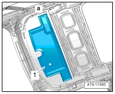
- Apply adhesive -arrows- on the roof reinforcement -1 and 2- as illustrated.
- Adhesive bead thickness: approximately 8 mm
- Apply the beads of adhesive according to the line markings on the roof reinforcement.
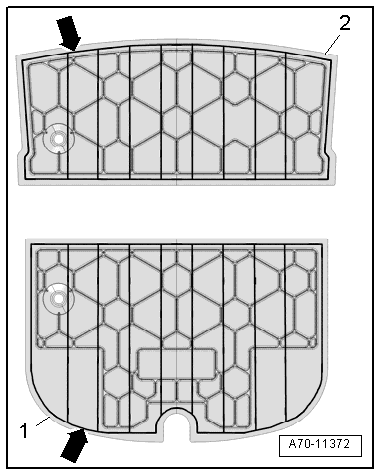
- Position the roof reinforcements -1 and 2- centered to the outer sides and at distance -a- to the bow -3- on the roof.
- Dimension -a- = 15 mm.
- Press the roof reinforcement on the roof surface.
- Wipe off any adhesive.
Installation is performed in reverse order of removal, noting the following:
Installation notes, for example tightening specifications, replacing components. Refer to → Chapter "Overview - Headliner, Sedan".
Roof Reinforcement, Attaching to Body, Sedan with Sunroof
Special tools and workshop equipment required
- For the correct assembly adhesive. Refer to the Parts Catalog.
Procedure
- Remove the headliner and lay it on the seats, do not remove the windshield. Refer to → Chapter "Headliner, Removing and Installing, Sedan".
Caution
- Remove the headliner and lay it on the seats when performing the following work. Do this very carefully because the headliner can be creased easily.
- Replace the headliner if it is bent.
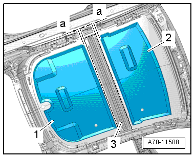
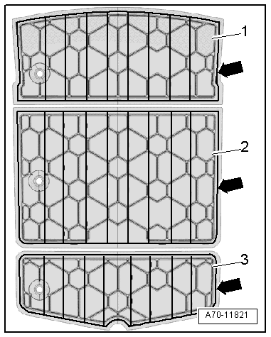
- Using the markings as a guide, apply a bead of adhesive -arrow- onto the roof reinforcement as illustrated.
- Adhesive bead thickness: approximately 8 mm
- Apply the beads of adhesive according to the line markings on the roof reinforcement.
- Mount roof reinforcement -1- centered between the outer sides and at a distance -a- from the bow on the roof.
- Dimension -a- = 33 mm.
- Press the roof reinforcement on the roof surface.
- Wipe off any adhesive.
Installation is performed in reverse order of removal, noting the following:
Installation notes, for example tightening specifications, replacing components. Refer to → Chapter "Overview - Headliner, Sedan".
Roof Reinforcement, Attaching to Body, Avant without Sunroof
Special tools and workshop equipment required
- For the correct assembly adhesive. Refer to the Parts Catalog.
Procedure
- Remove the headliner. Refer to → Chapter "Headliner, Removing and Installing, Sedan".
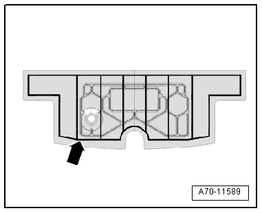
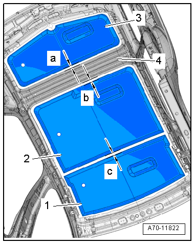
- Apply adhesive beads -arrows- to the roof reinforcement as shown in the illustration.
- Adhesive bead thickness: approximately 8 mm
- Apply the beads of adhesive according to the line markings on the roof reinforcement.
1 - Front roof reinforcement
2 - Center roof reinforcement
3 - Rear roof reinforcement
- Attach the center roof reinforcements -2 and 3-, to the outsides and in the spaces -a and b- for the rail -4- on the roof.
- Attach the center roof reinforcement -1- to the outside and in the space -c- for the center roof reinforcement.
- Dimension -a- = 15 mm.
- Dimension -b- = 20 mm
- Dimension -c- = 10 mm
- Press the roof reinforcement on the roof surface.
- Wipe off any adhesive.
 Note
Note
For vehicles with additional roof rails, the roof reinforcements -1- and -2- must fit at the height of the B-pillar.
Install in reverse order of removal.
- Install the headliner. Refer to → Chapter "Headliner, Removing and Installing, Avant".
Installation notes, for example tightening specifications, replacing components. Refer to → Chapter "Overview - Headliner, Sedan".
Special Tools
Special tools and workshop equipment required
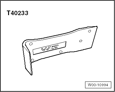
- Removal Wedge -T40233-
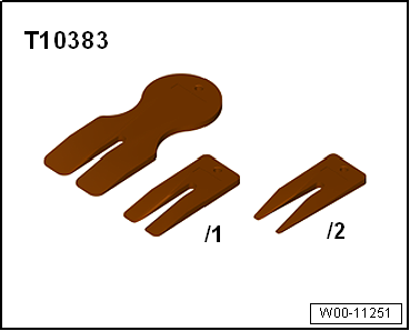
- Wedge Set -T10383-
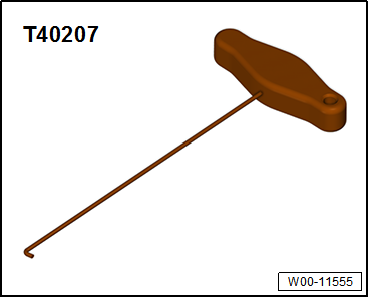
- Hook Tool -T40207-
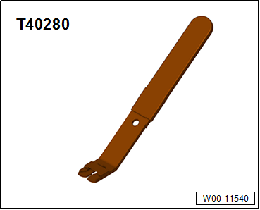
- Omega Clip Tool -T40280-
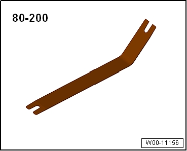
- Pry Lever -80-200-
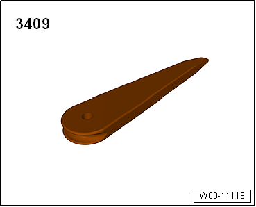
- Trim Removal Wedge -3409-