Audi A6 Typ 4G: Rear Brake Caliper, Removing and Installing
Brake Caliper, Removing and Installing, Steel Brakes
Special tools and workshop equipment required
- Torque Wrench 1332 40-200Nm -VAG1332-
 Caution
This procedure contains mandatory replaceable parts. Refer to component overview and parts catalog prior to starting procedure.
Mandatory Replacement Parts
- Bolts - Connector to brake caliper
- Bolts - Stub axle carrier to brake carrier
- O-ring - Electromechanical Parking Brake Motor
 Note
Note
In the following description the brake caliper is removed with the brake carrier and brake pads. The brake hose remains connected.
Removing
- Loosen the parking brake.
- Switch off the ignition.
Note
Do not disconnect the connectors from the parking brake motors.
- Remove the affected rear wheel. Refer to → Suspension, Wheels, Steering; Rep. Gr.44; Wheels, Tires.
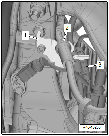
- Free up the brake hose -2- and the wiring harness -3- from the bracket -1-.
Note
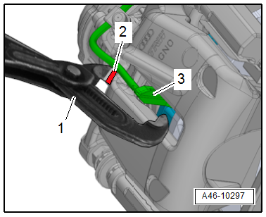
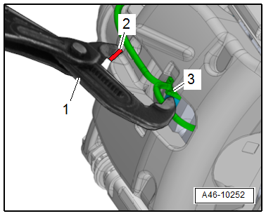
- Pushing on the inner brake pad lightly with pliers -1- makes it easier to remove the brake caliper from the brake rotor. To prevent damage to the paint coat on the brake caliper, place a piece of rubber -2- between the pliers and brake caliper.
- Do not damage the brake pad wear sensor contact -3-.
- Remove the brake carrier bolts -arrows-.
- Remove the brake caliper with brake carrier and installed brake pads from the brake rotor.
Note
If the brake rotor is so worn that the brake caliper cannot be removed, then the parking brake must be driven back. Refer to → Chapter "Brake Pads, Removing and Installing, Steel Brakes".
Caution
There is a risk of damaging the brake hose.
- Do not let the brake caliper hang on the brake hose. Do not support the weight with the brake hose.
- Replace the brake hose if damaged.
There is a risk of damaging the brake caliper piston.
Do not operate the brakes or the electromechanical parking brake when the brake caliper is removed.
- Hang the brake caliper with the brake carrier on the body using suitable wire.
Installing
Install in reverse order of removal and note the following:
Note
Replace the brake carrier bolts after removing.
 WARNING
Health Risk.
Do not blow out brake system with compressed air.
Note
Use only mineral spirits to clean the brake caliper.
- Carefully slide the brake caliper with the brake carrier and the installed brake pads over the brake rotor.
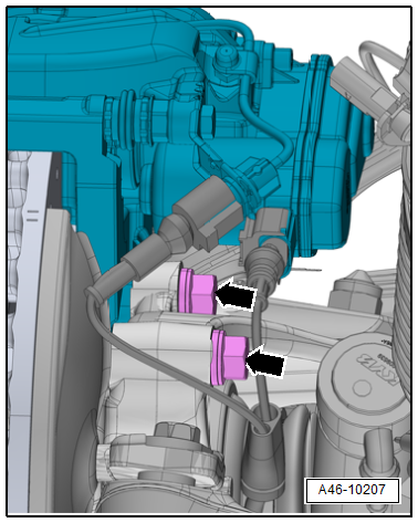
- Tighten the new brake carrier bolts -arrows-.
- Secure the brake hose -2- and wiring harness -3- in the bracket -1-.
Note
- Make sure that the wire and brake hose are routed correctly.
- Make sure the brake hose is not blocked, bent, twisted or rubbing against the vehicle.
- Install the rear wheel. Refer to → Suspension, Wheels, Steering; Rep. Gr.44; Wheels, Tires.
- Drive the parking brake motors up using the Vehicle Diagnostic Tester by following the instructions in the display.
WARNING
Risk of accident!
- With the vehicle stationary, firmly press the brake pedal several times so that the brake pads in the operating condition properly sit in their respective position.
- Make sure the brakes are working correctly before driving the vehicle for the first time.
Brake Caliper, Removing and Installing, Ceramic Brakes
Special tools and workshop equipment required
- Torque Wrench 1332 40-200Nm -VAG1332-
Caution
This procedure contains mandatory replaceable parts. Refer to component overview and parts catalog prior to starting procedure.
Mandatory Replacement Parts
- Bolts - Connector to brake caliper
- Bolts - Stub axle carrier to brake carrier
- O-ring - Electromechanical Parking Brake Motor
Note
In the following description the brake caliper is removed with the brake carrier and brake pads. The brake hose remains connected.
Removing
- Loosen the parking brake.
- Switch off the ignition.
Note
Do not disconnect the connectors from the parking brake motors.
- Remove the affected rear wheel, while observing the safety precautions for vehicles with ceramic brakes. Refer to → Suspension, Wheels and Steering; Rep. Gr.44; Wheels, Tires.
- Free up the brake hose -2- and the wiring harness -3- from the bracket -1-.
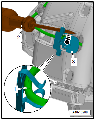
- Unclip the bracket -3- with a screwdriver -2--arrow-.
- Free up the brake pad wear indicator wire -1-.
Note
- Pushing on the inner brake pad lightly with pliers -1- makes it easier to remove the brake caliper from the brake rotor. To prevent damage to the paint coat on the brake caliper, place a piece of rubber -2- between the pliers and brake caliper.
- Do not damage the brake pad wear sensor contact -3-.
- Remove the brake carrier bolts -arrows-.
- Carefully remove the brake caliper with brake carrier and brake pads installed from the brake rotor.
Note
If the brake rotor is so worn that the brake caliper cannot be removed, then the parking brake must be driven back. Refer to → Chapter "Brake Pads, Removing and Installing, Ceramic Brakes".
Caution
There is a risk of damaging the brake hose.
- Do not let the brake caliper hang on the brake hose. Do not support the weight with the brake hose.
- Replace the brake hose if damaged.
There is a risk of damaging the brake caliper piston.
Do not operate the brakes or the electromechanical parking brake when the brake caliper is removed.
- Hang the brake caliper with the brake carrier on the body using suitable wire.
Installing
Install in reverse order of removal and note the following:
Note
Replace the brake carrier bolts after removing.
WARNING
Health Risk.
Do not blow out brake system with compressed air.
Note
Use only mineral spirits to clean the brake caliper.
- Carefully slide the brake caliper with the brake carrier and the installed brake pads over the brake rotor.
- Tighten the new brake carrier bolts -arrows-.
- Guide the brake pad wear indicator wire -1- into the bracket -3- as shown.
- Clip the bracket into the brake caliper.
Note
Ignore -item 2- and -arrow-.
- Press the brake hose -2- and wiring harness -3- into the bracket -1-.
Note
- Make sure the wire are installed correctly in the brackets on the stub axle carrier so that they can come out of the brackets on their own.
- Make sure the brake hose is routed correctly.
- Make sure the brake hose is not blocked, bent or rubbing against the vehicle.
- Install the rear wheel, while observing the safety precautions for vehicles with ceramic brakes. Refer to → Suspension, Wheels and Steering; Rep. Gr.44; Wheels, Tires.
- Drive the parking brake motors up using the Vehicle Diagnostic Tester by following the instructions in the display.
WARNING
Risk of accident!
- With the vehicle stationary, firmly press the brake pedal several times so that the brake pads in the operating condition properly sit in their respective position.
- Make sure the brakes are working correctly before driving the vehicle for the first time.
