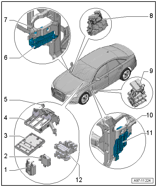
Audi A6 Typ 4G: Overview - Relay Carriers, Fuse Panels and E-Boxes
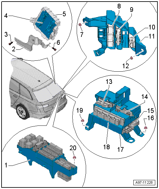
Overview - Relay Carriers, Fuse Panels and E-Boxes
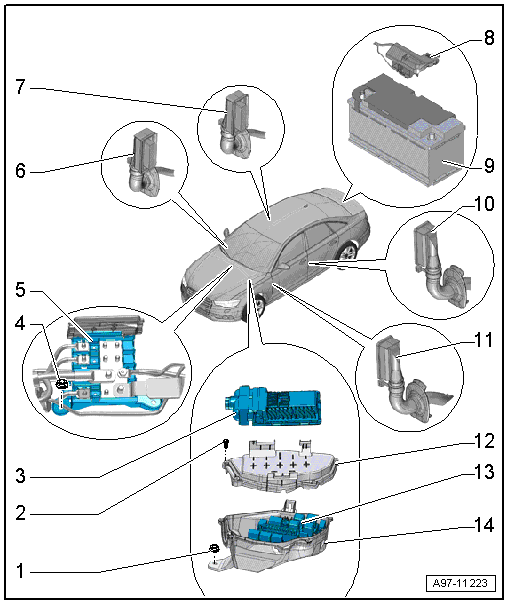
1 - Nut
- 3 Nm
- Quantity: 2
2 - Screw
- 3 Nm
- Quantity: 4
3 - Engine Control Module
4 - Nut
- 3 Nm
- Quantity: 2
5 - Terminal 30 Wire Junction -TV2-
- Removing and installing. Refer to → Chapter "Terminal 30 Wire Junction -TV2-, Removing and Installing".
6 - Right Front Door Cut-Off Connector
- Component location overview. Refer to → Chapter "Overview - Connector".
7 - Right Rear Door Cut-Off Connector
- Component location overview. Refer to → Chapter "Overview - Connector".
8 - Main Fuse Panel
- In the luggage compartment on the battery
- Removing and installing. Refer to → Chapter "Main Fuse Panel in Luggage Compartment, Removing and Installing".
9 - Battery
10 - Left Rear Door Cut-Off Connector
- Component location overview. Refer to → Chapter "Overview - Connector".
11 - Left Front Door Cut-Off Connector
- Component location overview. Refer to → Chapter "Overview - Connector".
12 - Cover
- For the plenum chamber E-box
13 - Relay Panel Inside Plenum Chamber E-Box
- Removing and installing. Refer to → Chapter "Relay and Fuse Panel in Plenum Chamber E-Box, Removing and Installing".
- With Fuse Panel A -SA-, removing and installing. Refer to → Chapter "Fuse Panel A -SA-, Removing and Installing, in Plenum Chamber E-box".
- With Suppressor -C24-, removing and installing. Refer to → Chapter "Suppressor -C24-, Removing and Installing".
14 - Plenum Chamber E-Box
- Removing and installing. Refer to → Chapter "E-Box, Removing and Installing".
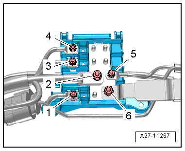
Terminal 30 Wire Junction -TV2- Tightening Specifications:
1 - PTC Wire - 18 Nm
2 - Battery Jump Start Terminal -U6- - 20 Nm
3 - Nut - 7.5 Nm
4 - Nut - 7.5 Nm
5 - E-box positive cable - 7.5 Nm
6 - Battery Cable - 18 Nm
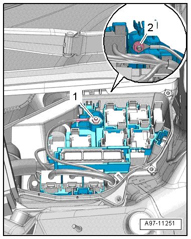
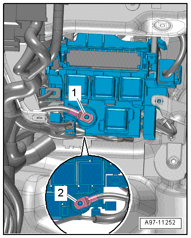
Tightening Specification for the Relay Panel and Fuse Panel inside the Plenum Chamber E-Box
1 - Positive wire - 9 Nm
2 - Wire on the back - 9 Nm
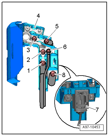
Tightening Specification for the Main Fuse Panel
1 - Electric wire - 7.5 Nm
2 - Nut - 9 Nm
3 - Nut - 9 Nm
4 - Main fuse panel inside the luggage compartment
5 - Positive Cable to Engine - 7.5 Nm
6 - Screw - 3.5 Nm
7 - Battery Interrupt Igniter -N253-. Refer to → Body Interior; Rep. Gr.69; Battery Interrupt Igniter; Battery Interrupt Igniter, Removing and Installing.
8 - Wire - 18 Nm
Overview - Relay Carrier, Fuse Panel, E-Boxes, with High Voltage System
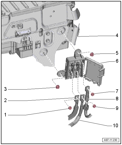
1 - Nut
- 7.5 Nm
2 - Electrical Wire
- To the Electric Drive Power and Control Electronics -JX1-
3 - Nut
- 4 Nm
4 - Mount
- For the Electric Drive Power and Control Electronics -JX1-
5 - Nut
- 4 Nm
6 - Terminal 30 Wire Junction 2 -TV22-
- Removing and installing. Refer to → Chapter "Terminal 30 Wire Junction 2 - TV22-, Removing and Installing, with High Voltage System".
7 - Nut
- 7.5 Nm
8 - Electrical Wire
- To the Terminal 30 Wire Junction -TV2-
9 - Nut
- 7.5 Nm
10 - Electrical Wire
- To the Power Steering Control Module -J500-
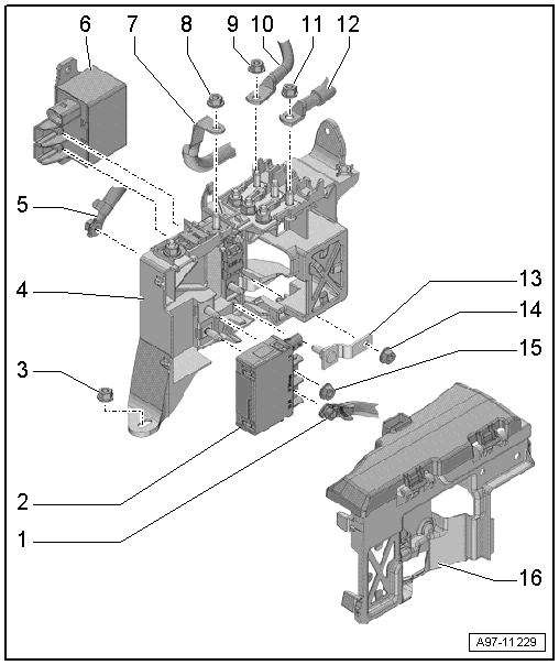
Overview - Relay Carrier, Instrument Panel, E-Boxes Fuse Carrier
1 - Mount
- For the Headlamp Range Control Module -J431-
- Removing and installing. Refer to → Chapter "Relay Panel Mount, Removing and Installing, Under Instrument Panel and Left Side, Vehicle Electrical System Control Module -J519-".
2 - Headlamp Range Control Module -J431-
- Overview. Refer to → Chapter "Overview - Automatic Head Lamp Range Control".
3 - Vehicle Electrical System Control Module -J519-
- Removing and installing. Refer to → Chapter "Vehicle Electrical System Control Module -J519-, Removing and Installing".
4 - Mount
- For the Vehicle Electrical System Control Module -J519- and relay panel
- Removing and installing. Refer to → Chapter "Relay Panel Mount, Removing and Installing, Under Instrument Panel and Left Side, Vehicle Electrical System Control Module -J519-".
5 - Nut
- 3 Nm
- Quantity: 2
6 - Fuse Panel C -SC- on the right side of the instrument panel
- Removing and installing. Refer to → Chapter "Fuse Panel C -SC- with Right Instrument Panel Fuse Panel, Removing and Installing".
- Fuse carrier, removing and installing. Refer to → Chapter "Right Instrument Panel Fuse Carrier, Removing and Installing".
7 - Right Central Tube
8 - Connector Station on Right A-Pillar
- Component location overview. Refer to → Chapter "Overview - Connector".
9 - Connector Station on Left A-Pillar
- With 46-Pin Connector -T46a-
- Component location overview. Refer to → Chapter "Overview - Connector".
10 - Left Central Tube
11 - Fuse Panel B -SB- on Left Side of Instrument Panel
- Removing and installing. Refer to → Chapter "Fuse Panel B -SB- with Left Instrument Panel Fuse Panel, Removing and Installing".
- Fuse carrier, removing and installing. Refer to → Chapter "Left Instrument Panel Fuse Carrier, Removing and Installing".
12 - Relay Carrier Under Left Instrument Panel
- Removing and installing. Refer to → Chapter "Relay Carrier under Left Instrument Panel, Removing and Installing".
Tightening Specification for the Relay Carrier under the Instrument Panel on the Left Side with a Threaded Connection
1 - Wire - 9 Nm
2 - Wire on the back - 9 Nm
Overview - Relay Panel, Fuse Panel, E-Boxes, Luggage Compartment, Sedan
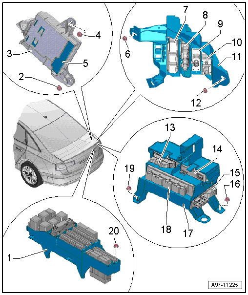
1 - Relay and Fuse Panel F -SF-
- Removing and installing. Refer to → Chapter "Fuse Panel F -SF- in Right Luggage Compartment, Removing and Installing".
- With Fuse Panel F -SF-, Removing and installing. Refer to → Chapter "Fuse Panel in Right Luggage Compartment, Removing and Installing".
- With 46-Pin Connector -T46b-, Component Location Overview. Refer to → Chapter "Overview - Connector".
2 - Nut
- 3 Nm
3 - Frame
- For the control module
4 - Nut
- 3 Nm
5 - Comfort System Central Control Module -J393-
- Removing and installing. Refer to → Body Exterior; Rep. Gr.57; Central Locking; Comfort System Central Control ModuleJ393, Removing and Installing.
6 - Nut
- 3 Nm
7 - Towing Recognition Control Module -J345-
- Overview. Refer to → Chapter "Overview - Outlet, Towing Recognition Control Module".
8 - Vehicle Positioning System Interface Control Module -J843-
- Removing and installing. Refer to → Body Exterior; Rep. Gr.57; Central Locking; Component Location Overview - Central Locking.
9 - Not Assigned
10 - Parking Heater Radio Receiver -R64-
- Not available for North American market
11 - Upper Frame
- For the control modules
12 - Nut
- 3 Nm
13 - Parking Aid Control Module -J446-/Parallel Parking Assistance Control Module -J791-
- Overview. Refer to → Chapter "Overview - Parking Aid".
14 - Cellular Telephone Amplifier -R86-
- Removing and installing. Refer to → Communication; Rep. Gr.91; Telephone System; Cellular Telephone Amplifier R86, Removing and Installing.
15 - Rearview Camera System Control Module -J772-
- Removing and installing. Refer to → Communication; Rep. Gr.91; Rearview Camera System; Rearview Camera System Control Module J772, Removing and Installing
16 - Nut
- 3 Nm
17 - Lower Frame
- For the control modules
18 - Level Control System Control Module -J197-
- Removing and installing. Refer to → Suspension, Wheels, Steering; Rep. Gr.43; Air Suspension; Level Control System Control Module J197, Removing and Installing
19 - Nut
- 3 Nm
20 - Nut
- 3 Nm
Overview - Relay Panel, Fuse Panel, E-Boxes, Luggage Compartment, Avant
1 - Relay and Fuse Panel F -SF-
- Removing and installing. Refer to → Chapter "Fuse Panel F -SF- in Right Luggage Compartment, Removing and Installing".
- With Fuse Panel F -SF-, Removing and installing. Refer to → Chapter "Fuse Panel in Right Luggage Compartment, Removing and Installing".
- With 46-Pin Connector -T46b-, Component Location Overview. Refer to → Chapter "Overview - Connector".
2 - Bracket
- For the release lever for the remote release for the backrest
3 - Screw
- Tightening specification: Refer to → Body Interior; Rep. Gr.72; Rear Seats; Overview - Locking Mechanism
4 - Comfort System Central Control Module -J393-
- Removing and installing. Refer to → Body Exterior; Rep. Gr.57; Central Locking; Comfort System Central Control ModuleJ393, Removing and Installing.
5 - Frame
- For the control module
6 - Screw
- Tightening specification: Refer to → Body Interior; Rep. Gr.72; Rear Seats; Overview - Locking Mechanism
7 - Nut
- 3 Nm
8 - Towing Recognition Control Module -J345-
- Overview. Refer to → Chapter "Overview - Outlet, Towing Recognition Control Module".
9 - Vehicle Positioning System Interface Control Module -J843-
- Removing and installing. Refer to → Body Exterior; Rep. Gr.57; Central Locking; Component Location Overview - Central Locking.
10 - Parking Heater Radio Receiver -R64-
- Not available for North American market
11 - Upper Frame
- For the control modules
12 - Nut
- 3 Nm
13 - Parking Aid Control Module -J446-/Parallel Parking Assistance Control Module -J791-
- Overview. Refer to → Chapter "Overview - Parking Aid".
14 - Cellular Telephone Amplifier -R86-
- Removing and installing. Refer to → Communication; Rep. Gr.91; Telephone System; Cellular Telephone Amplifier R86, Removing and Installing.
15 - Rearview Camera System Control Module -J772-
- Removing and installing. Refer to → Communication; Rep. Gr.91; Rearview Camera System; Rearview Camera System Control Module J772, Removing and Installing
16 - Nut
- 3 Nm
17 - Lower Frame
- For the control modules
18 - Level Control System Control Module -J197-
- Removing and installing. Refer to → Suspension, Wheels, Steering; Rep. Gr.43; Air Suspension; Level Control System Control Module J197, Removing and Installing
19 - Nut
- 3 Nm
20 - Nut
- 3 Nm
Overview - Relay Panel, Fuse Panel, E-Boxes, Luggage Compartment, with High Voltage System
1 - Positive Cable
- 9 Nm
- To the main fuse panel on the Battery -A-
2 - Starter Battery Switch-Over Relay -J580-
- Removing and installing. Refer to → Chapter "Starter Battery Switch-Over Relay -J580-, Removing and Installing".
3 - Nut
- 3 Nm
- Quantity: 2
4 - Wire Junction -TV1-
- Removing and installing. Refer to → Chapter "Wire Junction -TV1-, Removing and Installing, with High Voltage System".
5 - Positive Cable
- 9 Nm
- To the Auxiliary Battery -A1-
6 - Battery Cut-Out Relay -J7-
- Removing and installing. Refer to → Chapter "Battery Cut-Out Relay -J7-, Removing and Installing".
7 - Electrical Wire
- To the Terminal 30 Wire Junction -TV2-
8 - Nut
- 9 Nm
9 - Nut
- 7.5 Nm
10 - Ground Cable
11 - Nut
- 7.5 Nm
12 - Positive Cable
- To the relay/fuse panel, right control modules
13 - Conductor Rail
14 - Nut
- 9 Nm
15 - Nut
- 9 Nm
16 - Cover
- For Wire Junction -TV1-
