Audi A6 Typ 4G: Tire Pressure Monitoring System
Tire Pressure Monitoring with Pressure Sensor
 WARNING
If tire sealant was used, then the wheel electronics on that particular wheel must be replaced.
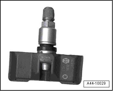
The wheel electronics, that is, the system pressure sensor, forms a physical unit with the valve.
 Note
Note
The lettering on the wheel electronics shows which system is installed.
 Note
Note
Currently there are two versions of the wheel electronics.
Beru TPMS. Refer to → Chapter "Wheel Electronics System (Tire Pressure Monitoring System), Beru ".
Siemens TPMS. Refer to → Chapter "Wheel Electronics System (Tire Pressure Monitoring System), Siemens ".
Direct measuring systems according to model → Chapter "Metal Valve Body, Removing and Installing".
Indirect measuring systems according to model → Chapter "Metal Valve Body, Removing and Installing".
Overview, Beru System
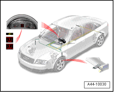
The pressure sensor transfers the recorded signals to the tire pressure monitoring system antenna.
The pressure sensor is connected firmly to the rim with a threaded connection.
If the tire pressure drops, the driver is warned via the pressure sensor in the instrument cluster.

Tire Pressure Monitoring System
To inform the driver, this system transfers the tire pressure values via a control module to the driver information system in the instrument cluster.
 Note
Note
- If vehicles with tire pressure monitoring sensors are transported in airplanes, the airline must be informed of the sensors.
- The correct allocation must be observed, otherwise the tire pressure monitoring will not function correctly.
More detailed information on this system can be found in SSP 219 "Electronic tire pressure monitoring".

Tire Pressure Monitoring System with Wheel Speed Sensor
 WARNING
Tires with emergency running characteristics are only installed in conjunction with a tire pressure monitoring system.
 Note
Note
If the vehicle has TPMS, there are no wheel electronics in the rim.
 Note
Note
The lettering on the wheel electronics shows which system is installed.
Beru wheel electronics system. Refer to → Chapter "Wheel Electronics System (Tire Pressure Monitoring System), Beru ".
Siemens wheel electronics system. Refer to → Chapter "Wheel Electronics System (Tire Pressure Monitoring System), Siemens ".
Direct measuring systems according to model → Chapter "Metal Valve Body, Removing and Installing".
Indirect measuring systems according to model → Chapter "Metal Valve Body, Removing and Installing".
When the tire pressure decreases, the speed of the respective tire changes.
The changed tire speed is recorded by the speed sensor.
The driver is informed of the changed tire pressure in the instrument cluster.
Emergency Wheels
Emergency Wheels, Using
 Note
Note
Inform your customer as necessary of the notes listed in the following and also refer if necessary to the vehicle Owner's Manual.
The following notes listed also apply to spare wheels that are marked with a yellow sticker with the note "MAX 80 km/h" or "MAX 50 mph".
 Note
Note
- Emergency wheel/spare wheel is designed only for sporadic and brief use. Therefore it is to be replaced with the normal wheel again as soon as possible.
- After mounting the emergency wheel/spare wheel, tire inflation pressure must be checked as soon as possible. The correct tire inflation pressure can be found in the following tire inflation pressure table on the respective vehicle or the respective manual: Maintenance.
- Always pay attention to speed information on the wheel ("MAX 80 km/h" or "MAX 50 mph").
- Wide Open Throttle (WOT) acceleration, strong braking and rapid driving around curves should be prevented.
- Never drive with more than one emergency wheel/spare wheel.
- It is not permissible to use snow chains on the emergency wheel for technical reasons.
- If vehicle must be driven with snow chains, therefore the emergency wheel must be installed on the rear axle for a breakdown on the front axle. The rear wheel freed up must then be mounted in place of the faulty front wheel.

