Audi A6 Typ 4G: Battery, Disconnecting and Connecting
Battery, Disconnecting and Connecting, Vehicles without High Voltage System
 Caution
Accident risk.
When working on pyrotechnic components (such as airbags and belt tensioners), the battery must be disconnected with the ignition switched on, contrary to the following description.
TDI (SCR) vehicles
- After the ignition is switched off, the reducing agent goes from the metering line to the Reducing Agent Injector -N474- and back into the reducing agent active chamber.
- Wait until all the reducing agent has been returned before working in this area. This could take up to 10 minutes after switching off the ignition.
- Only after this is complete can the battery be disconnected. Again, this could take up to 10 minutes after switching off the ignition.
Disconnecting
- Turn off the ignition.
- Lift the luggage compartment floor covering by the handle and fold it forward.
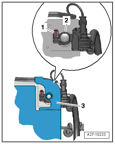
- Open the cover -3- over the battery negative pole.
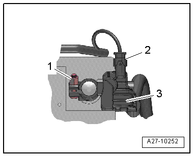
- Loosen the nut -1- several turns and remove the battery ground cable terminal -2- from the battery terminal.
Connecting
- Disconnect the connector -2- from the Battery Monitoring Control Module -J367--item 3-.
- Connect the battery ground cable terminal to the battery negative pole "-" by hand and tighten the nut -1-.
- Reconnect the connector to the Battery Monitoring Control Module -J367-.
When the battery is connected, the following steps must be performed:
- Activate the one-touch up/one-touch down power window regulators. Refer to the Owner's Manual.
- Check DTC memories of all control modules and erase "Undervoltage" DTC if necessary using the Vehicle Diagnostic Tester.
 Note
Note
After connecting the power supply, the ABS warning lamp may only go out after the vehicle has been driven a few yards.
Battery -A- and Auxiliary Battery -A1-, Disconnecting and Connecting, Vehicles with High Voltage System
 WARNING
Both the Battery -A- and the Auxiliary Battery -A1- must always be disconnected at the same time to de-energize the 12 volt system.
DANGER!
Damaged high voltage components may produce dangerously high voltage.
Note the following when working near high voltage components and cables:
- Do not use tools that have sharp edges, that are used for cutting or shaping, or that generate heat, such as welding, soldering, hot air or thermal adhesive equipment.
- Inspect the high voltage components in the area where the work will be performed before starting the procedure.
- Perform a visual inspection of the Electric Drive Power and Control Electronics -JX1-, the Electro-Drive Drive Motor -V141-, the Electrical A/C Compressor -V470- and the high voltage cables when working inside the engine compartment.
- Perform a visual inspection of the high voltage cables and the covers when working on the floor panel.
- Perform a visual inspection of the high voltage cables and the electro-box with the High Voltage System Maintenance Connector -TW- when working in the rear of the vehicle.
- Perform a visual inspection of all of the potential equalization cables.
Note the following when performing the visual inspection:
- None of the components may display any exterior damage.
- The high voltage cable insulation and the potential equalization cables may not be damaged.
- The high voltage cables may not be deformed in any way.
- Each high voltage component muss be labeled with a red warning label.
Disconnecting
- Remove the luggage compartment floor. Refer to → Body Interior; Rep. Gr.70; Luggage Compartment Trim Panels; Luggage Compartment Floor Panel, Removing and Installing.
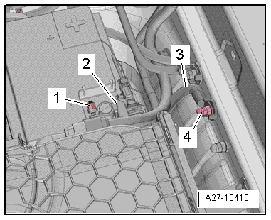
- Remove the nut -4- from the ground point and the ground cable -3-.
Caution
Immediately wrap the connection for the ground cable with insulating tape and set it aside.
- Loosen the nut -1- several turns and remove the battery ground cable terminal -2- from the battery negative terminal.
Caution
Immediately wrap the battery ground cable terminal with insulating tape and set it aside.
Connecting
- Attach the battery ground cable terminal -2- by hand to the battery negative pole "-" when attaching the Auxiliary Battery -A1-, and then tighten the nut -1-.
- Tighten the ground cable -3- to the ground connection.
When the batteries are connected, the following steps must be performed:
- Activate the one-touch up/one-touch down power window regulators. Refer to the Owner's Manual.
- Check DTC memories of all control modules and erase "Under voltage" DTC if necessary using the Vehicle Diagnostic Tester.
Note
After connecting the power supply, the ABS warning lamp may only go out after the vehicle has been driven a few yards.
