Audi A6 Typ 4G: Vehicle Diagnosis, Testing and Information Systems
 WARNING
- During road tests using a vehicle diagnostic and information system, there is the hazard of extreme to lethal injuries!
- If vehicle diagnostic and information system is deposited in the action area of an airbag during a road test, here is the hazard of extreme to lethal injuries in the event the airbag deploys!
- During road tests, have a person sitting in the rear seat to operate the vehicle diagnostic and information system.
Audi TT and Audi R8
WARNING
- During road tests using a Vehicle Diagnostic Tester, there is the hazard of extreme to lethal injuries!
- If vehicle diagnostic and information system is deposited in the action area of an airbag during a road test, here is the hazard of extreme to lethal injuries in the event the airbag deploys!
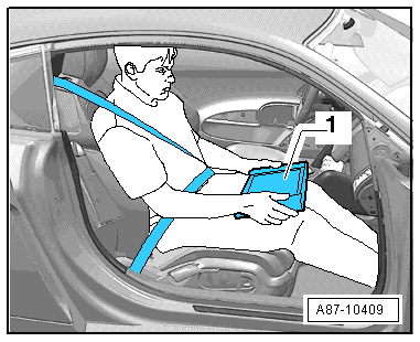
- During road tests, have a person sitting in the front passenger seat in the rearmost position to operate the Vehicle Diagnostic Tester.
- TheVehicle Diagnostic Tester-1- must lie flat on the passenger's legs and be operated by that person, as shown in the illustration.
- Connect the Vehicle Diagnostic Tester. Refer to → Chapter "Vehicle Diagnostic Tester, Connecting".
Vehicle Diagnostic Tester, Connecting
Special tools and workshop equipment required
- Vehicle Diagnostic Tester and diagnostic cable
Procedure
- Engage the parking brake or operate the electromechanical parking brake.
- Shift the shifter lever into neutral or place the selector lever in the "P" position.
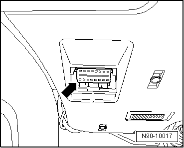
- Turn off the ignition and connect the Vehicle Diagnostic Tester to the Data Link Connector (DLC) with the diagnostic cable -arrow-.
- When using the Remote Diagnosis Head -VAS5054A- or the Diagnosis Interface -VAS5055- pay attention to the Operating Instructions.
- Turn on the ignition.
- Turn off all electrical consumers.
 Note
Note
If a error message appears on the screen of the Vehicle Diagnostic Tester. Refer to the Operating Instructions.