Audi A6 Typ 4G: Overview - Instrument Panel
Overview - Instrument Panel
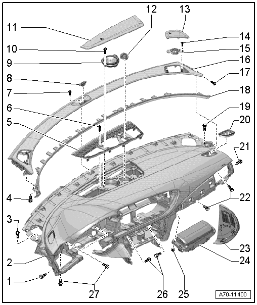
1 - Bolt
- 3 Nm
2 - Instrument Panel
 WARNING
- Follow all Safety Precautions when working with pyrotechnic components. Refer to → Chapter "Pyrotechnic Components Safety Precautions".
- Follow the allocation of the airbag to the instrument panel. Refer to the Parts Catalog.
- Removing and installing. Refer to → Chapter "Instrument Panel, Removing and Installing".
3 - Bolt
- 3 Nm
4 - Bolt
- 1.5 Nm
- Quantity: 12
5 - Defroster Vent in the Center
- Removing and installing. Refer to → Chapter "Front Center Defroster Vent, Removing and Installing".
6 - Bolt
- 1.5 Nm
- Quantity: 2
7 - Bolt
- 1.5 Nm
8 - Sunlight Photo Sensor -G107-
- Removing and installing. Refer to → Heating, Ventilation and Air Conditioning; Rep. Gr.87; Additional Components for Control and Regulation; Sunlight Photo Sensor G107, Removing and Installing.
9 - Center Speaker -R208-
- Equipment levels
- Removing and installing. Refer to → Communication; Rep. Gr.91; Sound System; Center Speaker, Removing and Installing.
10 - Bolt
- Tightening specification. Refer to → Communication; Rep. Gr.91; Sound System; Component Location Overview - Sound System.
11 - Center Speaker Trim
- Removing and installing. Refer to → Chapter "Center Speaker Trim, Removing and Installing".
- First, insert in the front of the instrument panel and press on it until it engages audibly.
12 - Center Speaker 2 -R219-
- Equipment levels
- Removing and installing. Refer to → Communication; Rep. Gr.91; Sound System; Center Speaker, Removing and Installing.
13 - Side Speaker Trim
- Quantity: 2
- Removing and installing. Refer to → Chapter "Side Speaker Trim, Removing and Installing".
- First, insert in the front of the instrument panel and press on it until it engages audibly.
14 - Bolt
- Tightening specification. Refer to → Communication; Rep. Gr.91; Sound System; Component Location Overview - Sound System.
15 - Left Front Treble Speaker -R20-
- Right: Right Front Treble Speaker -R22-
- Equipment levels
- Removing and installing. Refer to → Communication; Rep. Gr.91; Sound System; Front Treble Speakers, Removing and Installing.
16 - Upper Instrument Panel Cover
- Removing and installing. Refer to → Chapter "Instrument Panel Upper Cover, Removing and Installing".
17 - Bolt
- 1.5 Nm
- Quantity: 2
18 - Trim Strip
- For the instrument panel cover
- Removing and installing. Refer to → Chapter "Instrument Panel Upper Cover, Removing and Installing".
19 - Bolt
- 3 Nm
20 - Side Defroster Vent
- Removing and installing. Refer to → Chapter "Side Defroster Vent, Removing and Installing".
- Press on it until it locks
21 - Bolt
- 3 Nm
22 - Screws
- 3 Nm
23 - Side Cover
- For the instrument panel
- Removing and installing. Refer to → Chapter "Instrument Panel Side Cover, Removing and Installing".
- Press on until it engages audibly
24 - Front Passenger Airbag
- With the Front Passenger Airbag Igniter 1 -N131- and Front Passenger Airbag Release Valve Igniter -N491-
- Market-specific with Front Passenger Airbag Igniter 2 -N132-
WARNING
- Follow all Safety Precautions when working with pyrotechnic components. Refer to → Chapter "Pyrotechnic Components Safety Precautions".
- Follow the allocation of the airbag to the instrument panel. Refer to the Parts Catalog.
- Overview. Refer to → Chapter "Overview - Front Passenger Airbag".
- Locking and activating possible with key switch
25 - Nut
- Tightening specification. Refer to → Chapter "Overview - Front Passenger Airbag".
26 - Screws
- 3 Nm
27 - Screws
- 3 Nm
Overview - Instrument Panel, Installation Components
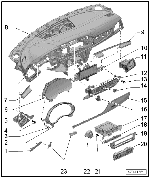
1 - Driver Side Trim
- For the instrument panel
- Clipped in to the instrument panel
- Removing and installing. Refer to → Chapter "Instrument Panel Decorative Trim, Removing and Installing, Driver Side".
2 - Frame
- For the instrument cluster
- Removing and installing. Refer to → Chapter "Instrument Cluster Frame, Removing and Installing".
3 - Bolt
- 3 Nm
- Quantity: 4
4 - Bolt
- 3 Nm
5 - Instrument Panel Vent
- For driver side
- Removing and installing. Refer to → Chapter "Driver Side Instrument Panel Vent, Removing and Installing".
- Replace damaged or deformed clips
- When sliding it into the installation opening, make sure the air duct engages correctly.
- Press it into the installation opening as far as the stop.
6 - Instrument Cluster
- Removing and installing. Refer to → Electrical Equipment; Rep. Gr.90; Instrument Cluster; Overview - Instrument Cluster.
7 - Instrument Panel Cover
- Removing and installing. Refer to → Chapter "Instrument Panel Rear Cover, Removing and Installing".
- Replace damaged or deformed clips
- Press on until it engages audibly
8 - Instrument Panel
WARNING
- Follow all Safety Precautions when working with pyrotechnic components. Refer to → Chapter "Pyrotechnic Components Safety Precautions".
- Follow the allocation of the airbag to the instrument panel. Refer to the Parts Catalog.
- Removing and installing. Refer to → Chapter "Instrument Panel, Removing and Installing".
9 - Instrument Panel Cover
- Removing and installing. Refer to → Chapter "Instrument Panel Rear Cover, Removing and Installing".
- Replace damaged or deformed clips
- Press on until it engages audibly
10 - Front Information Display Control Head -J685-
- Removing and installing. Refer to → Communication; Rep. Gr.91; Infotainment System; Infotainment System Display, Removing and Installing.
11 - Instrument Panel Vent
- For front passenger side
- Removing and installing. Refer to → Chapter "Passenger Side Instrument Panel Vent, Removing and Installing".
12 - Center Instrument Panel Vent
- Removing and installing. Refer to → Chapter "Center Instrument Panel Vent, Removing and Installing".
13 - Bolt
- 3 Nm
- Quantity: 2
14 - Emergency Flasher Button -E229-
- Removing and installing. Refer to → Electrical Equipment; Rep. Gr.96; Controls; Emergency Flasher Button E229, Removing and Installing.
15 - Front Passenger Side Trim
- For the instrument panel
- Clipped in to the instrument panel
- Removing and installing. Refer to → Chapter "Instrument Panel Decorative Trim, Removing and Installing, Front Passenger Side".
- Press on until it engages audibly
16 - Front Display Open/Close Button -E462-/Display Unit Button -E506-
- Removing and installing. Refer to → Electrical Equipment; Rep. Gr.96; Controls; Overview - Center Console Controls.
17 - Information Electronics Control Module 1 -J794-
- Equipment levels
- Removing and installing. Refer to → Communication; Rep. Gr.91; Infotainment System; Information Electronics Control Module 1J794, Removing and Installing.
18 - Switch Unit
- With Start/Stop Mode Button -E693-, Parallel Parking Assistance Button -E581-, Parking Aid Button -E266-, Front Passenger Airbag -Disabled- Indicator Lamp -K145-, Rear Spoiler Adjustment Switch -E127- and ASR/ESP Button -E256-
- Removing and installing. Refer to → Electrical Equipment; Rep. Gr.96; Controls; Overview - Instrument Panel Controls.
19 - Trim
- For Information Electronics Control Module 1 -J794-
- Removing and installing. Refer to → Communication; Rep. Gr.91; Infotainment System; Information Electronics Control Module 1J794, Removing and Installing.
20 - Climatronic Control Module -J255-
- Removing and installing. Refer to → Heating, Ventilation and Air Conditioning; Rep. Gr.87; Display and Control Head; Display and Control Head, Removing and Installing.
21 - Bolt
- Quantity: 4
- Tightening specification. Refer to → Communication; Rep. Gr.91; Infotainment System; Component Location Overview - Infotainment System.
22 - Anti-Theft Immobilizer Reader Coil -D2-
- Removing and installing. Refer to → Electrical Equipment; Rep. Gr.96; Immobilizer; Anti-Theft Immobilizer Reader Coil, Removing and Installing.
23 - Instrument Cluster Gap Cover
- Removing and installing. Refer to → Chapter "Instrument Cluster Gap Cover, Removing and Installing".
Overview - Instrument Panel, Windshield Projection (Head Up Display)
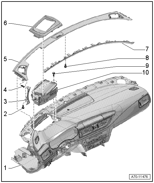
1 - Instrument Panel
WARNING
- Follow all Safety Precautions when working with pyrotechnic components. Refer to → Chapter "Pyrotechnic Components Safety Precautions".
- Follow the allocation of the airbag to the instrument panel. Refer to the Parts Catalog.
- Removing and installing. Refer to → Chapter "Instrument Panel, Removing and Installing".
2 - Bolt
- Tightening specification -item 4-
3 - Trim Strip
- For the instrument panel cover
- Removing and installing. Refer to → Chapter "Instrument Panel Upper Cover, Removing and Installing".
4 - Bolt
- Tightening specification -item 17-
5 - Upper Instrument Panel Cover
- Removing and installing. Refer to → Chapter "Instrument Panel Upper Cover, Removing and Installing".
6 - Cover
- For Windshield Projection Head Up Display Control Module -J898-
- Removing and installing. Refer to → Chapter "Instrument Panel Upper Cover, Removing and Installing".
- Press on until it engages audibly
7 - Trim Strip
- For the instrument panel cover
- Removing and installing. Refer to → Chapter "Instrument Panel Upper Cover, Removing and Installing".
8 - Bolt
- Tightening specification -item 4-
9 - Bolt
- Tightening specification. Refer to → Electrical Equipment; Rep. Gr.90; Instrument Cluster; Overview - Windshield Projection Head Up Display.
10 - Windshield Projection Head Up Display Control Module -J898-
- Removing and installing. Refer to → Electrical Equipment; Rep. Gr.90; Instrument Cluster; Windshield Projection Head Up Display Control Module, Removing and Installing.
