Audi A6 Typ 4G: Bulkhead
Overview - Bulkhead
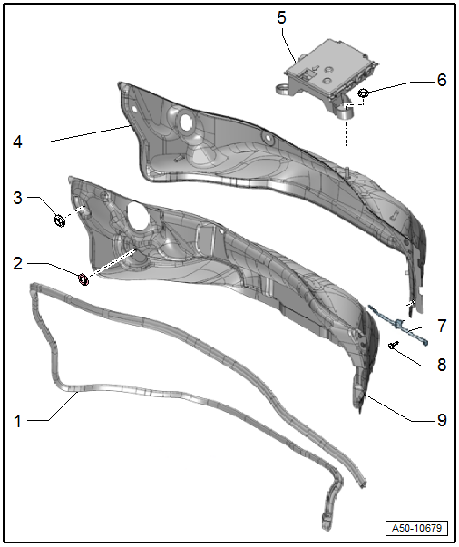
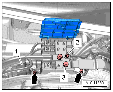
1 - Seal
- Install on the plenum chamber bulkhead
2 - Lock Washer
- Quantity: 2
3 - Nut
- 4 Nm
4 - Plenum Chamber Bulkhead
- There are different versions. Refer to the Parts Catalog.
- Removing and installing. Refer to → Chapter "Plenum Chamber Bulkhead, Removing and Installing".
5 - Terminal 30 Wire Junction -TV2-
- Removing and installing. Refer to → Electrical Equipment; Rep. Gr.97; Relay Carriers, Fuse Panels and E-Boxes; Overview - Relay Carriers, Fuse Panels and E-Boxes.
6 - Nut
- Tightening specification. Refer to → Electrical Equipment; Rep. Gr.97; Relay Carriers, Fuse Panels and E-Boxes; Overview - Relay Carriers, Fuse Panels and E-Boxes.
7 - Cable Bracket
- There are different versions. Refer to the Parts Catalog.
8 - Bolt
- 2 Nm
- There are different versions. Refer to the Parts Catalog.
9 - Heat Shield
- Overview. Refer to → Chapter "Overview - Heat Shield".
Overview - Plenum Chamber Cover
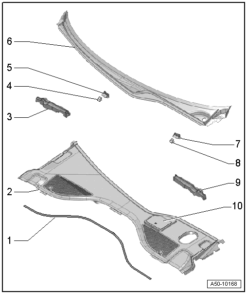
1 - Seal
- Replace if damaged.
2 - Plenum Chamber Cover
- Removing and installing. Refer to → Chapter "Plenum Chamber Cover, Removing and Installing".
3 - Right Foam Piece
4 - Clip
5 - Right Mount
- For clip
6 - Cowl Panel Trim
- Removing and installing. Refer to → Chapter "Cowl, Removing and Installing".
7 - Left Mount
- For clip
8 - Clip
9 - Left Foam Piece
10 - Cover
- For the brake fluid reservoir
Plenum Chamber Bulkhead, Removing and Installing
Special tools and workshop equipment required
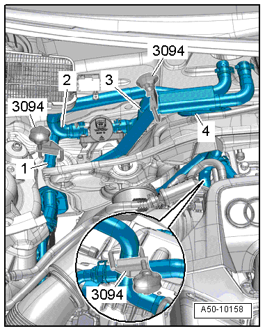
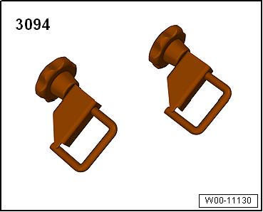
- Hose Clamps - Up To 25 mm -3094-
Removing
- Remove the tower brace. Refer to → Suspension, Wheels, Steering; Rep. Gr.40; Suspension Strut and Upper Control Arm; Tower Brace, Removing and Installing.
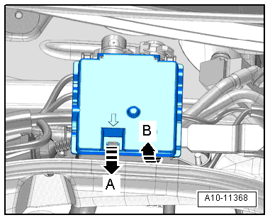
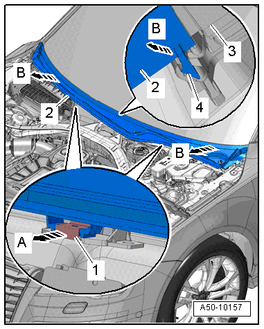
- Release the retainer -arrow A- and open the cover -arrow B-.
- Remove the nut -3- and free up the wire.
- Remove the connector -1- from the bracket.
- Remove the nuts -arrows- and then remove Terminal 30 Wire Junction 2 -TV22- from the plenum chamber bulkhead.
 Note
Note
Ignore -item 2-.
- Free up the wiring harness on the plenum chamber bulkhead.
Vehicles with a Gasoline Engine:
- Cover the area under the shut-off valve with an absorbent cloth or paper.
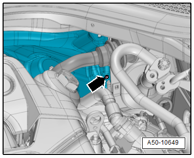
- Clamp off the coolant hoses -1 and 3- with Hose Clamps - Up To 25mm -3094-.
- Open the clamps and remove the coolant hose -2- from the shut-off valve.
- Remove the grommet -4- on the plenum chamber bulkhead to the engine.
Note
A vehicle with an auxiliary heater is shown in the illustration.
Continuation for all Vehicles:
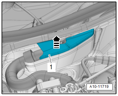
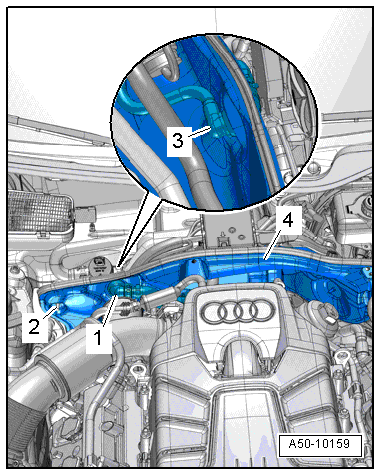
- Remove the heat shield -1- upward -arrow-, if equipped.
- Release the retainers -A arrows- and remove the wiring bushing -1- upward -arrow B-.
- Remove the bolt -arrow-.
Note
Different types of fasteners may be installed. There can be a cable bracket, clip or bolt.
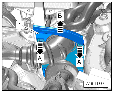
- Remove the brake booster vacuum line -3-.
- Remove the grommet -1- from the vacuum connection.
- Remove the nut -2- and then remove the plenum chamber bulkhead -4- upward.
Installing
- Tightening specification: Refer to → Chapter "Overview - Bulkhead".
Install in reverse order of removal. Note the following:
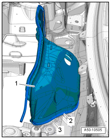
- Make sure the seal -2- on the plenum chamber bulkhead -1- fits correctly into the mount -3- on the plenum chamber.
- Check the coolant level. Refer to → Rep. Gr.19; Coolant System/Coolant; Coolant, Draining and Filling.
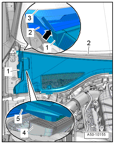
Plenum Chamber Cover, Removing and Installing
Plenum Chamber Cover, Removing and Installing
Removing
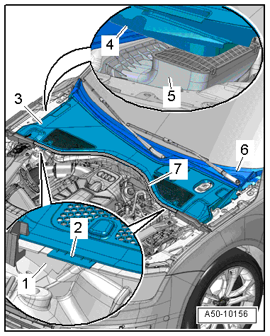
- Remove the seal -7-.
- Lift the plenum chamber cover -3- far enough so that the frame -4- is above the air intake shroud -5- for the fresh air blower.
- Remove the plenum chamber cover from the cowl panel -6-.
Note
The tab -2- over the cover -1- will get damaged if the seal is not removed.
Installing
Install in reverse order of removal. Note the following:
Note
- Be careful not to damage the plenum chamber cover -2- and the plenum chamber cover with frame -5- for the air intake shroud -4- to prevent water from getting into the air conditioner when the plenum chamber cover is installed -1-.
- The plenum chamber cover cowl panel must lock completely into the windshield frame -3-.
- The plenum chamber cover must be installed correctly and completely into the mount -arrow- for cowl panel.
Cowl, Removing and Installing
Removing
- Remove the plenum chamber cover. Refer to → Chapter "Plenum Chamber Cover, Removing and Installing".
- Remove the windshield wiper arms. Refer to → Electrical Equipment; Rep. Gr.92; Windshield Wiper System; Windshield Wiper Arms, Removing and Installing.
- Remove the clip -1--arrow A-.
 Caution
Danger of causing damage to the wind cowl.
Coat the transition between the windshield and the cowl panel with a soapy solution.
- Remove the cowl panel -2- from the retainer -4- on the windshield -3- vertically upward -arrows B- starting on the edge of the glass.
Installing
Install in reverse order of removal. Note the following:
Note
- Be careful not to damage the cowl panel otherwise water can get into the air conditioner via the air intake shroud.
- The plenum chamber cover cowl panel must lock completely into the windshield frame.
Special Tools
Special tools and workshop equipment required
- Drill
- Brill diameter 4 mm.
- Hose Clamps - Up To 25 mm -3094-
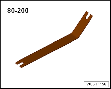
- Pry Lever -80 - 200-