Audi A6 Typ 4G: Relay and Fuse Panels In Luggage Compartment on Right Side, Removing and Installing
Fuse Panel F -SF- in Right Luggage Compartment, Removing and Installing
Removing
- With the ignition switched off, disconnect the ground cable from the battery. Refer to → Chapter "Battery, Disconnecting and Connecting".
- Remove the right luggage compartment trim panel.
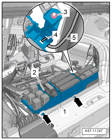
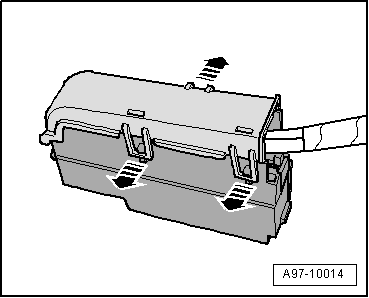
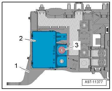
- Remove the nut -3-.
- Cut the cable tie -4- and free up the wiring harness -5-.
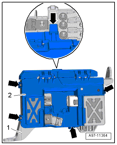
- Remove relay and fuse panel F -item 2- from the body -1--arrows-.
- Remove the mount for the 46-Pin Connector -T46b-. Refer to → Chapter "CAN Cut-Off Connector Mount, Removing and Installing".
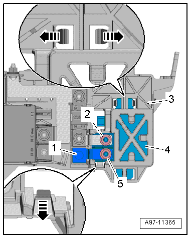
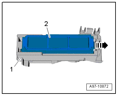
- Open the clip in direction of -arrow- and remove the fuse carrier -2- from the relay and fuse panel F -item 1-.
- Release the retainers in direction of -arrows- and remove the relay carrier -2- from the relay/fuse panel -1- to the rear.
- Remove the relay and fuse panel F.
 Note
Note
Check the exact connector assignment in the current wiring diagram → Wiring diagrams, Troubleshooting & Component locations.
Installing
Install in reverse order of removal. Note the following:
- Connect the battery. Required steps: vehicles without high voltage system. Refer to vehicles with high voltage system.
Fuse Panel in Right Luggage Compartment, Removing and Installing
Removing
- With the ignition switched off, disconnect the ground cable from the battery. Refer to → Chapter "Battery, Disconnecting and Connecting".
- Remove the relay and fuse panel F inside the luggage compartment on the right side. The relay mount remains clipped in. Refer to → Chapter "Fuse Panel F -SF- in Right Luggage Compartment, Removing and Installing".
- Unlock the release and remove it from the fuse carrier.
- Remove the fuses from the fuse carrier.
- Open the clips in direction of -arrows- and remove the fuse carrier cover.
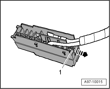
- Pull off retaining strip -1- for the connectors in direction of -arrow- and remove the connectors from the plug-in socket.
Note
Check the exact connector assignment in the current wiring diagram → Wiring diagrams, Troubleshooting & Component locations.
Installing
Install in reverse order of removal. Note the following:
- Connect the battery. Required steps: vehicles without high voltage system. Refer to vehicles with high voltage system.
Main Fuse Panel in Luggage Compartment, Removing and Installing
Removing
- Lift the luggage compartment floor covering by the handle and fold it forward.
- Vehicles with high voltage system: Remove the front outlet air guide for the traction battery. Refer to → Heating, Ventilation and Air Conditioning; Rep. Gr.87; Battery Cooling Module.
- Remove the cover over the battery positive terminal.
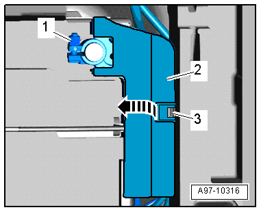
- Loosen the nut -1- a few turns and disconnect the battery positive cable terminal and the main fuse panel from the battery pole.
- Release the retaining spring -3- and open the flap -2- above the main fuse panel in direction of -arrow-.
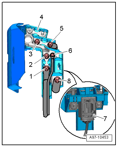
- Disconnect the electrical wires -1, 5, 6 and 8-.
Note
Ignore -items 2 and 3-.
- Remove the Battery Interrupt Igniter -N253--item 7-. Refer to → Body Interior; Rep. Gr.69; Battery Interrupt Igniter; Battery Interrupt Igniter, Removing and Installing.
- Remove the main fuse panel -4-.
Note
Check the exact connector assignment in the current wiring diagram → Wiring diagrams, Troubleshooting & Component locations.
Installing
Install in reverse order of removal.
Starter Battery Switch-Over Relay -J580-, Removing and Installing
Removing
- Remove the wire junction. Refer to → Chapter "Wire Junction -TV1-, Removing and Installing, with High Voltage System".
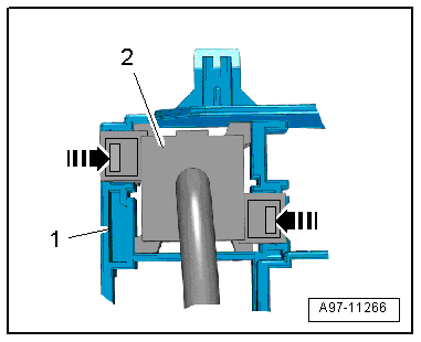
- Open the retainers -arrows- with a small screwdriver and remove the cover -2- from the wire junction -1-.
- Remove the nut -3-.
- Remove the starter battery switch-over relay -2- from the wire junction -1-.
Installing
Install in reverse order of removal.
Battery Cut-Out Relay -J7-, Removing and Installing
Removing
- Remove the wire junction. Refer to → Chapter "Wire Junction -TV1-, Removing and Installing, with High Voltage System".
- Open the retainers -arrows- with a small screwdriver and remove the cover -2- from the wire junction -1-.
- Remove the nuts -2 and 5-.
- Remove the connecting piece -1-.
- Open the tabs -arrows- and remove the battery cut-out relay -4- from the wire junction -3-.
Installing
Install in reverse order of removal.