Audi A6 Typ 4G: Air Supply Unit, Removing and Installing
Air Supply Unit with Bracket, Removing and Installing
Special tools and workshop equipment required
- Torque Wrench 1783 - 2-10Nm -VAG1783-
- Torque Wrench 1783 - Open Jaw - 10mm -VAG1783/1-
Removing
 Note
Note
The air supply unit is bolted to the bracket on the underbody (spare wheel well).
- Remove the air suspension system. Refer to → Chapter "System, Venting or Filling".
- If the control module is being replaced, then select "replace" control module on the Vehicle Diagnostic Tester in Guided Functions.
- Turn off the ignition.
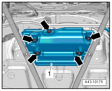
- Remove the nuts -arrows-.
- Remove the stone chip protection -1-.
Note
- Make sure no dirt gets into the pressure air system.
- Clean the area before removing connecting pieces for the air pipe lines or other components of the pressured air system.
- Seal off any open air lines and connections in the pressure system immediately with plugs or cover them.
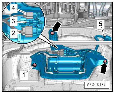
- Remove the connectors -2 and 4- from the bracket and disconnect them.
- Loosen the clamp -5- and remove the intake line.
- Remove the air line -3- from the bracket.
- Remove the nut -1- and the bolts -arrows-.
- Remove the bracket and air supply unit -5-.
Installing
Install in reverse order of removal. Note the following:
Note
- The vehicle may be removed from the vehicle hoist only after the air springs have been filled again. Refer to → Chapter "Raising and Lowering with Open and Closed Air Suspension System".
- Make sure the positioning pin on the air spring is installed correctly inside the body before filling the air suspension system. The air spring must be locked secure inside the wheel bearing housing at the same time. Refer to → Fig. "Air Spring Installed Position".
Air suspension system, filling. Refer to → Chapter "System, Venting or Filling".
If the air supply unit was replaced, then the Level Control System Compressor Relay -J403- must also be replaced. Installed location: → Wiring diagrams, Troubleshooting & Component locations.
Air Supply Unit, Removing and Installing
Special tools and workshop equipment required
- Torque Wrench 1783 - 2-10Nm -VAG1783-
Removing
- Remove the bracket and air supply unit. Refer to → Chapter "Air Supply Unit with Bracket, Removing and Installing".
Note
- Make sure no dirt gets into the pressure air system.
- Clean the area before removing connecting pieces for the air pipe lines or other components of the pressured air system.
- Seal off any open air lines and connections in the pressure system immediately with plugs or cover them.
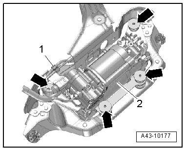
- Loosen the air line and electric wire out of the clip -1-.
- Remove the threaded sleeve -arrows- and the air supply unit -2-.
Installing
Install in reverse order of removal. Note the following:
Note
- The vehicle may be removed from the vehicle hoist only after the air springs have been filled again. Refer to → Chapter "Raising and Lowering with Open and Closed Air Suspension System".
- Make sure the positioning pin on the air spring is installed correctly inside the body before filling the air suspension system. The air spring must be locked secure inside the wheel bearing housing at the same time. Refer to → Fig. "Air Spring Installed Position".
If the air supply unit was replaced, then the Level Control System Compressor Relay -J403- must also be replaced. Installed location. Refer to → Wiring diagrams, Troubleshooting & Component locations.