Audi A6 Typ 4G: System Description - DRC
The DRC counteracts the pitching and rolling motions of the vehicle body around the longitudinal and cross axles and thus optimizes the vehicle driving characteristics. Switchable DRC with variable damping is installed in Audi RS models.
In addition to reducing the pitching and rolling motions of the vehicle body (identical to the hydraulic DRC), the adjustable DRC with variable damping allows the driver to adjust and the damping level using the Audi drive select controls. Each shock absorber has an additional component with an integrated electric motor. The Electronic Damping Control Module -J250- controls the electric motors.
There Are Several Damping Settings:
- "COMFORT"
- "DYNAMIC"
- "AUTO"
- "INDIVIDUAL"
Only approved oil for filling and draining must be used. Refer to the Parts Catalog.
 Caution
- Extracting, evacuating and filling the DRC line on vehicles with the variable damping may be performed only when the damping setting is set to "COMFORT".
- To extract, evacuate and fill the DRC line, start the Fill DRC"function" on the Vehicle Diagnostic Tester under address word 14 in "Guided Functions".
- If the mode is activated, the system goes into "COMFORT" mode and can no longer be changed manually. The yellow indicator lamp in the instrument cluster turns on when filling mode is active.
Filling must only be performed at ambient temperature of approximately 20 ºC (68 ºF).
As a replacement part, shock absorbers and lines are delivered empty.
Lines/shock absorbers and central valves may only be suctioned, evacuated and filled when they are installed and connected.
When the DRC system is disconnected from the individual components (for example, the connection between the line/shock absorber/central valve), the vehicle must not be standing on its wheels.
While filling the DRC system, the gas reservoir to the pressure clamps is checked for leaks on the piston on the inside of the central valve.
If, while filling of the DRC system, a pressure of 22 bar (319 psi) cannot be reached or continually drops, then check all connections for damage and leakage. If no issues are found on the outside, the gas reservoir to the pressure clamps on the piston on the inside of the central valve is leaking. Replace the central valve.
If the DRC system is being extracted, evacuated or filled, then this must be performed on the front and rear extraction/filling valves for each damper line. Note the following:
 WARNING
Always wear safety goggles!
Before removing or disconnecting any DRC components, extract the affected line completely.
Shock absorbers must only be filled when installed and connected.
Lines must not be bent.
A small oil leak at the connection that results from connecting or disconnecting the charging device DRC Pressure Tester -VAS6209/2- is not critical. Multiple measurements should be avoided since the system loses a little amount of oil each time the DRC Pressure Tester -VAS6209/2- is connected. Every connection results in a pressure decrease of approximately 0.3 bar (4.3 psi) from the previous reading. Multiple repeated measurements decrease system pressure below minimum pressure or failure.
Component Location Overview - Dynamic Ride Control
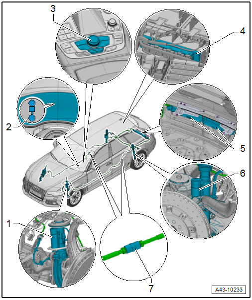
1 - Front Suspension Strut with Extract/Fill Valve.
- Additional component with an integrated electric motor - vehicle with variable damping
2 - Indicator Lamp
- Vehicle with variable damping
3 - Audi Drive Select Controls
- Vehicle with variable damping
4 - Electronic Damping Control Module -J250-
- Vehicle with variable damping
- Removing and installing. Refer to → Chapter "Electronic Damping Control Module -J250-, Removing and Installing".
5 - Central Valves
- Removing and installing. Refer to → Chapter "Central Valve, Removing and Installing".
6 - Rear Shock Absorber with Extract/Fill Valve.
- Additional component with an integrated electric motor - vehicle with variable damping
7 - Connection to the Right/Left Front Suspension Strut
- 14 Nm
Overview - Central Valve
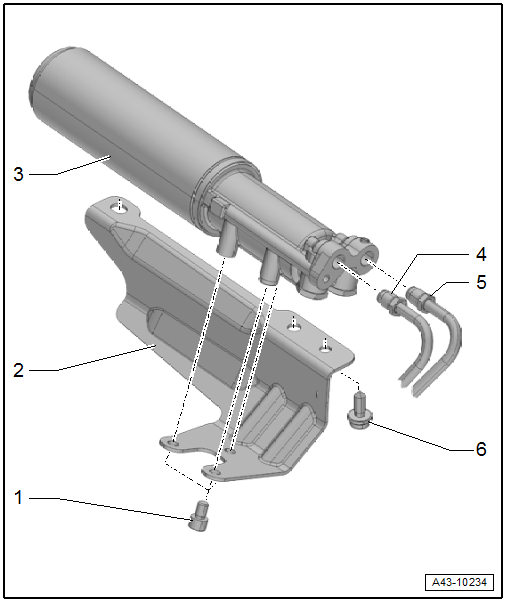
1 - Bolt
- 20 Nm
2 - Bracket
3 - Central Valve
- Removing and installing. Refer to → Chapter "Central Valve, Removing and Installing".
4 - DRC Line to Rear Shock Absorber
- 14 Nm
- Green marking at left
- Blue marking at right
5 - DRC Line to Front Shock Absorber
- 14 Nm
- Yellow marking at left
- White marking at right
6 - Bolt
- 20 Nm
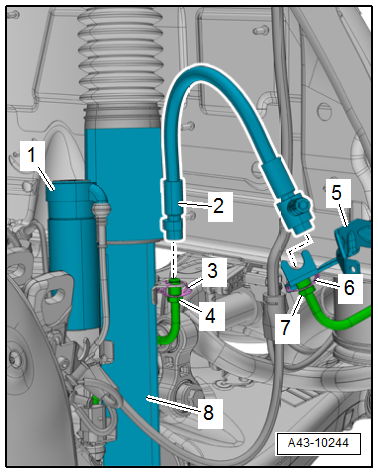
Front Suspension Strut
1 - Extract/fill valve with hose line, make sure it is free of tension when installed
2 - Bracket
3 - Clip
4 - Union nut, 14 Nm
5 - Additional element with motor, installed on vehicles with variable damping
6 - DRC shock absorber
7 - Union nut, 14 Nm
8 - Clip
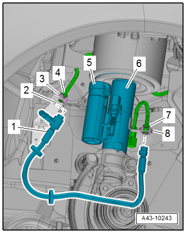
Rear Shock Absorber
1 - Additional element with motor, installed on vehicles with variable damping
2 - Extract/fill valve with hose line, make sure it is free of tension when installed
3 - Clip
4 - Union nut, 14 Nm
5 - Bracket
6 - Clip
7 - Union nut, 14 Nm
8 - DRC shock absorber