Audi A6 Typ 4G: Level Control System Solenoid -N111-, Removing and Installing
Special tools and workshop equipment required
- Torque Wrench 1783 - 2-10Nm -VAG1783-
Removing
 Note
Note
The Level Control System Solenoid -N111- is located on the air supply unit.
- Remove the air supply unit. Refer to → Chapter "Air Supply Unit, Removing and Installing".
Note
- Make sure no dirt gets into the pressure air system.
- Clean the area before removing connecting pieces for the air pipe lines or other components of the pressured air system.
- Seal off any open air lines and connections in the pressure system immediately with plugs or cover them.
- Disconnect the connector -3- from the Level Control System Solenoid -N111--2-.
- Remove the bolts -1-.
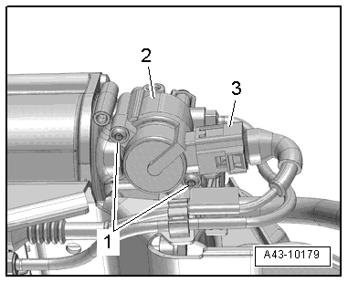
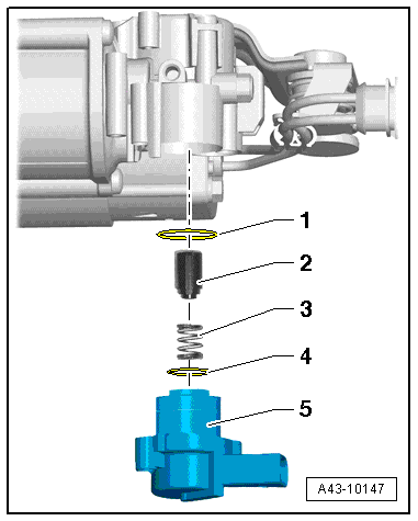
- Remove the Level Control System Solenoid -N111--5- with the O-rings -1 and 4-, the spring -3- and the anchor -2-.
Note
The O-ring -1- may still be located inside the air supply unit housing.
Installing
Install in reverse order of removal. Note the following:
Note
- The vehicle may be removed from the vehicle hoist only after the air springs have been filled again. Refer to → Chapter "Raising and Lowering with Open and Closed Air Suspension System".
- Make sure the positioning pin on the air spring is installed correctly inside the body before filling the air suspension system. The air spring must be locked secure inside the wheel bearing housing at the same time. Refer to → Fig. "Air Spring Installed Position".
Note
Always replace the O-rings.
- Coat the new O-rings -1 and 4- with the supplied grease.
- Note the anchor installation position -2-. The chamfer must point toward the spring -3-.
- Do not tilt the Level Control System Solenoid -N111- when installing it and when tightening the bolts.
- Air suspension system, filling → Chapter "System, Venting or Filling".
Solenoid Valve Block, Removing and Installing
Special tools and workshop equipment required
- Torque Wrench 1410 -VAG1410-
- Torque Wrench 1783 - 2-10Nm -VAG1783-
- Torque Wrench 1783 - Open Jaw - 10mm -VAG1783/1-
Removing
Note
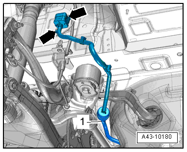
The solenoid valve block is located on the air supply unit.
- Place the vehicle on a hoist. Refer to → Chapter "Raising and Lowering with Open and Closed Air Suspension System".
- Vent the system. Refer to → Chapter "System, Venting or Filling".
- Turn off the ignition.
- Remove the luggage compartment floor covering. Refer to → Body Interior; Rep. Gr.70; Luggage Compartment Trim Panels; Overview - Luggage Compartment Floor or remove the spare tire.
Note
- Make sure no dirt gets into the pressure air system.
- Clean the area before removing connecting pieces for the air pipe lines or other components of the pressured air system.
- Seal off any open air lines and connections in the pressure system immediately with plugs or cover them.
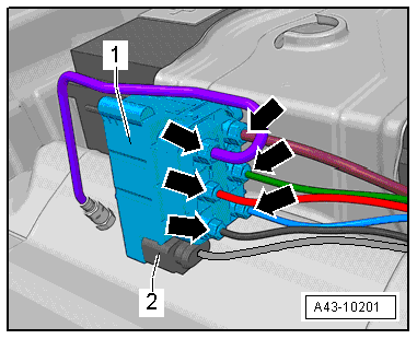
- Disconnect the connector -2-.
- Remove the air lines -arrows- and protect them immediately from dirt.
- Remove the solenoid valve block -1-.
Installing
Install in reverse order of removal. Note the following:
Note
- The vehicle may be removed from the vehicle hoist only after the air springs have been filled again. Refer to → Chapter "Raising and Lowering with Open and Closed Air Suspension System".
- Make sure the positioning pin on the air spring is installed correctly inside the body before filling the air suspension system. The air spring must be locked secure inside the wheel bearing housing at the same time. Refer to → Fig. "Air Spring Installed Position".
- Air suspension system, filling. Refer to → Chapter "System, Venting or Filling".
Intake Line with Filter, Removing and Installing
Special tools and workshop equipment required
- Torque Wrench 1783 - 2-10Nm -VAG1783-
Removing
- Remove the left rear wheel housing liner. Refer to → Body Exterior; Rep. Gr.66; Wheel Housing Liner; Rear Wheel Housing Liner, Removing and Installing.
Note
- Make sure no dirt gets into the pressure air system.
- Clean the area before removing connecting pieces for the air pipe lines or other components of the pressured air system.
- Seal off any open air lines and connections in the pressure system immediately with plugs or cover them.
- Remove the nuts -arrows-.
- Loosen the clamp -1- and remove the intake line and filter.
Installing
Install in reverse order of removal. Note the following:
- Install the left rear wheel housing liner. Refer to → Body Exterior; Rep. Gr.66; Wheel Housing Liner; Overview - Rear Wheel Housing Liner.
Pressure Reservoir, Removing and Installing
Special tools and workshop equipment required
- Torque Wrench 1783 - 2-10Nm -VAG1783-
- Vehicle Diagnostic Tester
Removing
Note
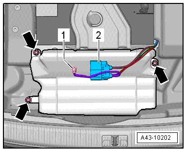
The pressure reservoir is installed inside the spare wheel well.
- Turn on the ignition.
- Bleed the pressure reservoir. Refer to → Chapter "System, Venting or Filling".
- Remove the tool box cover.
- Remove the solenoid valve block from the tool box and then remove the tool box.
Note
- Make sure no dirt gets into the pressure air system.
- Clean the area before removing connecting pieces for the air pipe lines or other components of the pressured air system.
- Seal off any open air lines and connections in the pressure system immediately with plugs or cover them.
- Slowly loosen air line -1- on pressure reservoir and allow air pressure to come down. After the air pressure has escaped, remove the air line.
- Remove the solenoid valve block -2- and move it to the side.
- Remove the nuts -arrows- and the pressure reservoir.
Installing
Install in reverse order of removal. Note the following:
- Fill the pressure reservoir. Refer to → Chapter "System, Venting or Filling".