Audi A6 Typ 4G: Airbag Crash Sensors
Component Location Overview - Airbag Crash Sensors
 Note
Note
The crash sensors in the Sedan are illustrated.
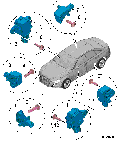
- 1 - Driver Front Airbag Crash Sensor -G283-
- Installation location: on the headlamp housing bracket
- Removing and installing. Refer to → Chapter "Front Airbag Crash Sensor -G283-/-G284-, Removing and Installing".
2 - Bolt
- 9 Nm
3 - Passenger Side Front Airbag Crash Sensor -G284-
- Installation location: on the headlamp housing bracket
- Removing and installing. Refer to → Chapter "Front Airbag Crash Sensor -G283-/-G284-, Removing and Installing".
4 - Bolt
- 9 Nm
5 - Front Passenger Side Airbag Crash Sensor -G180-
- Component location: inside the door
- Removing and installing. Refer to → Chapter "Driver Side Airbag Crash Sensor -G179-/Front Passenger Side Airbag Crash Sensor -G180-, Removing and Installing".
- For the safety precautions for working with front side airbag crash sensors (pressure sensors). Refer to → Chapter "Front Side Airbag Crash Sensors (Pressure Sensors) Safety Precautions".
6 - Bolt
- 5 Nm
- Quantity: 2
7 - Passenger Side Rear Side Airbag Crash Sensor -G257-
- Installed location: on the inside of the wheel housing behind the sill panel strip.
- Removing and installing. Refer to → Chapter "Driver Side Rear Side Airbag Crash Sensor -G256-/Passenger Side Rear Side Airbag Crash Sensor -G257-, Removing and Installing".
8 - Bolt
- 9 Nm
9 - Bolt
- 9 Nm
10 - Driver Side Rear Side Airbag Crash Sensor -G256-
- Installed location: on the inside of the wheel housing behind the sill panel strip.
- Removing and installing. Refer to → Chapter "Driver Side Rear Side Airbag Crash Sensor -G256-/Passenger Side Rear Side Airbag Crash Sensor -G257-, Removing and Installing".
11 - Driver Side Airbag Crash Sensor -G179-
- Component location: inside the door
- Removing and installing. Refer to → Chapter "Driver Side Airbag Crash Sensor -G179-/Front Passenger Side Airbag Crash Sensor -G180-, Removing and Installing".
- For the safety precautions for working with front side airbag crash sensors (pressure sensors). Refer to → Chapter "Front Side Airbag Crash Sensors (Pressure Sensors) Safety Precautions".
12 - Bolt
- 5 Nm
- Quantity: 2
Front Airbag Crash Sensor -G283-/-G284-, Removing and Installing
Removing
 WARNING
Follow all Safety Precautions when working with pyrotechnic components. Refer to → Chapter "Pyrotechnic Components Safety Precautions".
There is a risk of injury if the engine starts automatically in vehicles with the Start/Stop System.
- For vehicles with an activated Start/Stop system (recognized by a signal in the instrument cluster), the engine can be started automatically if needed.
- Make sure that the start/stop system is deactivated when working on the vehicle (turn off the ignition, turn on the ignition when necessary).
- Disconnect the battery Ground (GND) cable with the ignition turned on. Refer to → Electrical Equipment; Rep. Gr.27; Battery; Battery, Disconnecting and Connecting.
- Remove the front wheel housing liner. Refer to → Body Exterior; Rep. Gr.66; Wheel Housing Liner; Front Wheel Housing Liner, Removing and Installing.
- Remove the front wheel spoiler. Refer to → Body Exterior; Rep. Gr.66; Wheel Housing Liner; Front Wheel Housing Liner, Removing and Installing.
WARNING
Before handling pyrotechnic components (for example, disconnecting the connector), the person handling it must "discharge static electricity". This can be done by touching the door striker, for example.
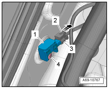
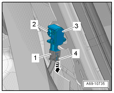
- Remove the bolt -2- and the front airbag crash sensor -3-.
- Pull out connector lock -4--arrow- and press down, disconnect harness connector -1- at the crash sensor.
Installing
WARNING
- Follow all Safety Precautions when working with pyrotechnic components. Refer to → Chapter "Pyrotechnic Components Safety Precautions".
- Before handling pyrotechnic components (for example, connecting the connector), the person handling it must "discharge static electricity". This can be done by touching the door striker, for example.
Install in reverse order of removal. Note the following:
Note
- Make sure the connectors are installed correctly and are secure.
- Make sure the wires do not get caught.
WARNING
Ignition must be on when connecting battery. If pyrotechnic components (for example, airbag, belt tensioner) are not repaired correctly, they may deploy unintentionally after connecting battery. There must not be anyone inside the vehicle when connecting the battery.
DANGER!
When working on vehicles with the ignition already switched on or that are ready to drive there is a danger of the engine starting unexpectedly and of being poisoned by gas in enclosed areas. Risk of body parts and/or clothing being clamped or pulled.
Perform the following before switching on the ignition:
- Move the selector lever into P.
- Activate the parking brake
- Turn off the ignition.
- Open the hood
- Connect the charger, such as the Battery Charger -VAS5095A- to the jump start of the 12V vehicle electrical system.
- Turn on the ignition.
- Connect the battery GND cable with the ignition turned on. Refer to → Electrical Equipment; Rep. Gr.27; Battery; Battery, Disconnecting and Connecting.
Note
If the Airbag Indicator Lamp -K75- indicates a fault, check the Diagnostic Trouble Code (DTC) memory, erase it and check it again. Refer to Vehicle Diagnostic Tester.
Installation notes, for example tightening specifications, replacing components. Refer to → Chapter "Component Location Overview - Airbag Crash Sensors".
Driver Side Airbag Crash Sensor -G179-/Front Passenger Side Airbag Crash Sensor -G180-, Removing and Installing
Removing
WARNING
- Follow all Safety Precautions when working with pyrotechnic components. Refer to → Chapter "Pyrotechnic Components Safety Precautions".
- Follow the safety precautions for front side airbag crash sensors (pressure sensors). Refer to → Chapter "Front Side Airbag Crash Sensors (Pressure Sensors) Safety Precautions".
- Disconnect the battery Ground (GND) cable with the ignition turned on. Refer to → Electrical Equipment; Rep. Gr.27; Battery; Battery, Disconnecting and Connecting.
- Remove the door trim panel. Refer to → Chapter "Front Door Trim Panel, Removing and Installing".
WARNING
Before handling pyrotechnic components (for example, disconnecting the connector), the person handling it must "discharge static electricity". This can be done by touching the door striker, for example.
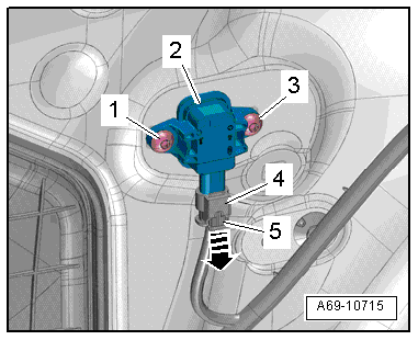
- Pull out the connector lock -5--arrow- and press down, then disconnect the connector -4- from the crash sensor.
- Remove the bolts -1 and 3- and the side airbag crash sensors -2-.
Installing
WARNING
- Follow all Safety Precautions when working with pyrotechnic components. Refer to → Chapter "Pyrotechnic Components Safety Precautions".
- Follow the safety precautions for front side airbag crash sensors (pressure sensors). Refer to → Chapter "Front Side Airbag Crash Sensors (Pressure Sensors) Safety Precautions".
- Before handling pyrotechnic components (for example, connecting the connector), the person handling it must "discharge static electricity". This can be done by touching the door striker, for example.
Install in reverse order of removal. Note the following:
Note
- Make sure the connectors are installed correctly and are secure.
- For proper crash sensor (pressure sensor) function, ensure door does not leak.
- All components (for example, cover, speaker, door trim) must be installed correctly.
- The door trim clips seal the system. Replace the clips if necessary.
- Make sure the wires do not get caught.
WARNING
Ignition must be on when connecting battery. If pyrotechnic components (for example, airbag, belt tensioner) are not repaired correctly, they may deploy unintentionally after connecting battery. There must not be anyone inside the vehicle when connecting the battery.
DANGER!
When working on vehicles with the ignition already switched on or that are ready to drive there is a danger of the engine starting unexpectedly and of being poisoned by gas in enclosed areas. Risk of body parts and/or clothing being clamped or pulled.
Perform the following before switching on the ignition:
- Move the selector lever into P.
- Activate the parking brake
- Turn off the ignition.
- Open the hood
- Connect the charger, such as the Battery Charger -VAS5095A- to the jump start of the 12V vehicle electrical system.
- Turn on the ignition.
- Connect the battery GND cable with the ignition turned on. Refer to → Electrical Equipment; Rep. Gr.27; Battery; Battery, Disconnecting and Connecting.
Note
If the Airbag Indicator Lamp -K75- indicates a fault, check the Diagnostic Trouble Code (DTC) memory, erase it and check it again. Refer to Vehicle Diagnostic Tester.
Installation notes, for example tightening specifications, replacing components. Refer to → Chapter "Component Location Overview - Airbag Crash Sensors".
Driver Side Rear Side Airbag Crash Sensor -G256-/Passenger Side Rear Side Airbag Crash Sensor -G257-, Removing and Installing
Removing
WARNING
- Follow all Safety Precautions when working with pyrotechnic components. Refer to → Chapter "Pyrotechnic Components Safety Precautions".
- Before handling pyrotechnic components (for example, disconnecting the connector), the person handling it must "discharge static electricity". This can be done by touching the door striker, for example.
- Disconnect the battery Ground (GND) cable with the ignition turned on. Refer to → Electrical Equipment; Rep. Gr.27; Battery; Battery, Disconnecting and Connecting.
- Remove the side cushion. Refer to → Chapter "Side Cushion, Removing and Installing".
- For vehicles with a fixed rear seat backrest: remove the rear seat backrest. Refer to → Chapter "Rear Seat Backrest, Removing and Installing".
- for vehicles with a Multi-contour seat: remove the Multi-contour seat. Refer to → Chapter "Rear Seat Backrest, Removing and Installing, Multi-contour Seat".
Driver Side Rear Side Airbag Crash Sensor -G256-:
WARNING
Before handling pyrotechnic components (for example, disconnecting the connector), the person handling it must "discharge static electricity". This can be done by touching the door striker, for example.
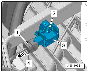
- Pull out connector lock -4- in direction of -arrow- and press down, disconnect harness connector -1- at the crash sensor.
- Remove the screw -2- and the side airbag crash sensors -3-.
Passenger Side Rear Side Airbag Crash Sensor -G257-:
WARNING
Before handling pyrotechnic components (for example, disconnecting the connector), the person handling it must "discharge static electricity". This can be done by touching the door striker, for example.
- Pull out the connector lock -2--arrow- and press down, then disconnect the connector -3- from the crash sensor.
- Remove the screw -4- and the side airbag crash sensors -1-.
Installing
WARNING
- Follow all Safety Precautions when working with pyrotechnic components. Refer to → Chapter "Pyrotechnic Components Safety Precautions".
- Before handling pyrotechnic components (for example, connecting the connector), the person handling it must "discharge static electricity". This can be done by touching the door striker, for example.
Install in reverse order of removal. Note the following:
Note
- Make sure the connectors are installed correctly and are secure.
- Make sure the wires do not get caught.
WARNING
Ignition must be on when connecting battery. If pyrotechnic components (for example, airbag, belt tensioner) are not repaired correctly, they may deploy unintentionally after connecting battery. There must not be anyone inside the vehicle when connecting the battery.
DANGER!
When working on vehicles with the ignition already switched on or that are ready to drive there is a danger of the engine starting unexpectedly and of being poisoned by gas in enclosed areas. Risk of body parts and/or clothing being clamped or pulled.
Perform the following before switching on the ignition:
- Move the selector lever into P.
- Activate the parking brake
- Turn off the ignition.
- Open the hood
- Connect the charger, such as the Battery Charger -VAS5095A- to the jump start of the 12V vehicle electrical system.
- Turn on the ignition.
- Connect the battery GND cable with the ignition turned on. Refer to → Electrical Equipment; Rep. Gr.27; Battery; Battery, Disconnecting and Connecting.
Note
If the Airbag Indicator Lamp -K75- indicates a fault, check the Diagnostic Trouble Code (DTC) memory, erase it and check it again. Refer to Vehicle Diagnostic Tester.
Installation notes, for example tightening specifications, replacing components. Refer to → Chapter "Component Location Overview - Airbag Crash Sensors".