Audi A6 Typ 4G: Final Drive, Removing and Installing
Final Drive Removing and Installing 0BC, Audi A4, A5, A6, A7, and Q% (not Q5 Hybrid)
Special tools and workshop equipment required
- Engine and Gearbox Jack -VAS6931- with Universal Transmission Support -VAG1359/2-
- Tensioning Strap -T10038-
- Engine/Gearbox Jack Adapter - Wheel Hub Support - T10149-
- Counterhold - Kit - Multiple Use -T10172- with Counterhold - Kit - Adapter 5 - T10172/5-
- Socket - Xzn 12 -T40154-
Removal
Pay attention to the general repair information. Refer to → Chapter "Repair Information".
- Place the vehicle on a lift.
- Remove the wheel hubcap from the left rear wheel. On alloy wheels, remove the cap using the puller in the vehicle tool kit.
- Remove the left rear wheel.
Vehicles with 6- or 8-Cylinder Engines (except for Q5)
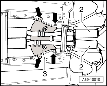
- Remove the rear crossmember -1-.
- Remove the rear section of the exhaust system -2-. Refer to → Rep. Gr.26; Exhaust Pipes/Mufflers; Overview - Muffler.
 Note
Note
A second technician is needed to help remove the rear section of the exhaust system.
- Secure the rear crossmember -1- again to the body.
Continuation for all Vehicles
- Remove the heat shield -3--arrows-.
- Remove the driveshaft from the rear final drive. Refer to → Chapter "Drive Shaft, Removing and Installing from Rear Final Drive".
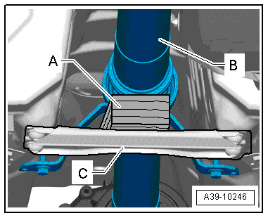
- Place a block of wood -A- (approximately 40 mm high) on the rear crossmember -C- and support the driveshaft -B-.
Note
- The driveshaft -B- is supported under the intermediate bearing by the heat shield on the Audi Q5.
- The driveshaft can be bent all the way to the center joint without force. Bending the joint forcibly all the way can damage the center joint and/or the protective boot.
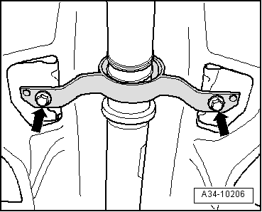
- Remove the driveshaft intermediate bearing mounting bolts -arrows-.
- Push the driveshaft forward and at the same time remove it from the rear final drive.
- Secure the driveshaft on the side to the subframe.
- Remove the left drive axle heat shield -A- from the crossmember/rear final drive -arrows-.
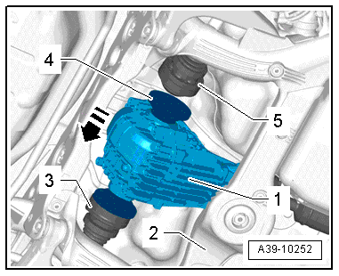
- Remove the left -1- and right -3- drive axles.
- Loosen the bolts -2- approximately three turns.
- Remove the bolt -4-.
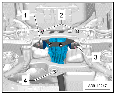
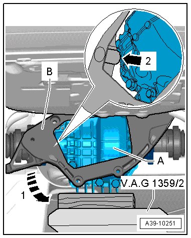
- Position the Engine and Gearbox Jack -VAS6931- and the Universal Transmission Support -VAG1359/2- and a block of wood -A- (approximately 80 mm tall) under the rear final drive.
Note
Pay attention that the Universal Transmission Support -VAG1359/2- does not make contact with the fuel tank.
- Remove the bolts -1- (lower bolts attaching the crossmember to the rear final drive) and -2-.
- Remove the two upper bolts that connect the crossmember -B- to the rear final drive.
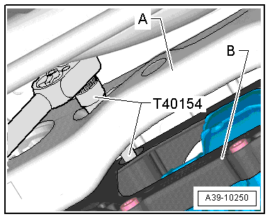
- Guide the Socket - Xzn 12 -T40154- through the holes in the subframe -A-. Move the final drive to the left or right just a little, if necessary.
- Move the final drive -A- forward slightly.
- Turn the lower crossmember -B- direction of -arrow 1- and guide the final drive -arrow 2- and remove it.
Note
- A second technician must help with the next steps.
- Before raising the left rear suspension, secure the vehicle to the lifting arm on the hose using a Tensioning Strap -T10038-.
- Remove the Engine and Gearbox Jack -VAS6931- from under the final drive while a second technician keeps the rear final driving from falling down.
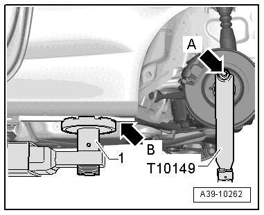
- Insert the Engine/Gearbox Jack Adapter - Wheel Hub Support - T10149- in the Engine and Gearbox Jack -VAS6931-.
- Attach the Engine/Gearbox Jack Adapter - Wheel Hub Support -T10149- using a wheel bolt -arrow A- to the left rear suspension wheel hub.
- Lift the left rear suspension using the Engine and Gearbox Jack -VAS6931- just until the support arm -1- on the vehicle hoist just starts to lift the vehicle -arrow B-.
 WARNING
- Do not raise or lower the vehicle when the Engine and Gearbox Jack -VAS6931- is underneath it.
- Do not leave the Engine and Gearbox Jack -VAS9631- under the vehicle longer than necessary.
- The second technician must now push the rear final drive -1- toward the left side of the vehicle in direction of -arrow-.
- Then guide the right drive axle -5- upward out of the final drive flange shaft -4-.
- Guide the left drive axle -3- out and then, together with the second technician, remove the final drive from the subframe -2- toward the rear.
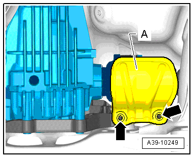
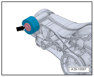
- If the rear final drive is replaced, the balance weight -arrow- must be rebuilt on the new rear final drive.
Installing
Install in reverse order of removal. Note the following:
- Tightening specifications. Refer to → Chapter "Overview - Final Drive 0BC, 0BD".
- With a second technician, position the rear final drive -1- on the subframe -2- in its installed position.
- Insert the left drive axle -3- into the final drive flange shaft.
- The second technician must now push the rear final drive -1- toward the left side of the vehicle in direction of -arrow-.
- Then install the right drive axle -5- into the final drive flange shaft -4-.
- Remove the Engine and Gearbox Jack -VAS6931- with the Engine/Gearbox Jack Adapter - Wheel Hub Support -T10149- from the left rear suspension.
- Position the Engine and Gearbox Jack -VAS6931- and the Universal Transmission Support -VAG1359/2- and a block of wood (approximately 80 mm tall) under the rear final drive -A-.
- Move the final drive -A- forward slightly.
- Turn the upper crossmember -B- opposite the direction of -arrow 1- to the left and insert it while guiding it past the final drive -arrow 2-.
- Tighten the four bolts connecting the crossmember -B- to the rear final drive diagonally. Tightening specification. Refer to -item 4-
- Guide the Socket - Xzn 12 -T40154- through the holes in the subframe -A-. Move the final drive to the left or right just a little, if necessary.
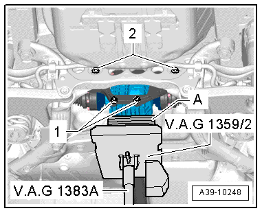
- First tighten the bolt -2 and 4- hand-tight.
Note
For better illustration the Engine and Gearbox Jack -VAS6931- with the Universal Transmission Support -VAG1359/2- are not shown.
- Tighten the bolt -4-. Tightening specification. Refer to -item 3-.
- Tighten the bolts -2-. Tightening specification. Refer to -item 2-.
- Remove the Engine and Gearbox Jack -VAS6931- from under the final drive.
- Tighten the left -1- and right -3- drive axles. Refer to → Suspension, Wheels, Steering; Rep. Gr.42; Drive Axle; Drive Axle, Removing and Installing.
- Attach the left drive axle heat shield -A- to the crossmember/rear final drive -arrows--item 6-.
- Attach the driveshaft to the rear final drive.
- Attach the driveshaft intermediate bearing to the body free of tension. Tightening specification. Refer to -item 8-.
- Check the gear oil level in the rear final drive. Refer to → Chapter "Gear Oil, Checking Level, 0BC".
- Attach the heat shield -3- to the body -arrows-.
- Install the rear section of the exhaust system and align it so it is free of tension. Refer to → Rep. Gr.26; Exhaust Pipes/Mufflers; Overview - Muffler.
- If equipped, install the cross member -1-. Refer to → Body Exterior; Rep. Gr.66; Underbody Panel; Overview - Underbody Panels.
- Install the left rear wheel and tighten. Refer to → Suspension, Wheels, Steering; Rep. Gr.44; Wheels and Tires.
Final Drive, Removing and Installing 0BF, Audi A4, A5, A6 and A7, Q5
Special tools and workshop equipment required
- Engine and Gearbox Jack -VAS6931- with Universal Transmission Support -VAG359/2-
- Tensioning Strap -T10038-
- Counterhold - Kit - Multiple Use -T10172- with Counterhold - Kit - Adapter 5 - T10172/5-
Removal
- Place the vehicle on a lift.
- Remove the wheel hubcap from the left rear wheel. On alloy wheels, remove the cap using the puller in the vehicle tool kit.
- Remove the rear wheels.
Note
Do not bend the flex joint in the front exhaust pipe more than 10º or it will be damaged.
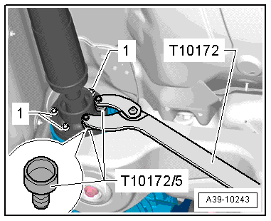
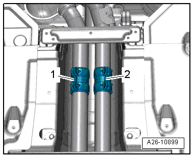
- Loosen the clamping sleeves -1 and 2- and disconnect the exhaust system.
- Attach the front exhaust pipe on the underbody side.
- If equipped, remove the rear crossmember -1-. Refer to → Body Exterior; Rep. Gr.66; Underbody Panel; Overview - Underbody Panels.
- Remove the rear section of the exhaust system -2-. Refer to → Rep. Gr.26; Exhaust Pipes/Mufflers; Overview - Muffler.
Note
A second technician is needed to help remove the rear section of the exhaust system.
- Remove the driveshaft. Refer to → Chapter "Driveshaft, Removing and Installing".
- Remove the left drive axle heat shield -A- from the rear final drive -arrows-.
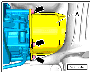
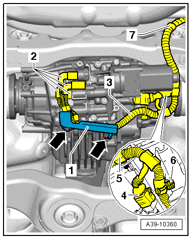
- Remove the bolts -arrows- and remove the bracket -1- from the rear final drive.
Note
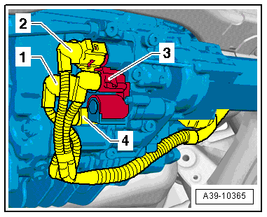
Mark the connectors -2- for the Oil Pressure/Temperature Sensor and on the Clutch Valves.
- Disconnect the connectors -2- from the Oil Pressure/Temperature Sensor and the Clutch Valves.
- Disconnect the connector -4- from the All Wheel Drive Pump -V415-.
- Unclip the wiring harness -3- from the final drive and the subframe and tie it up -items 5 through 7-.
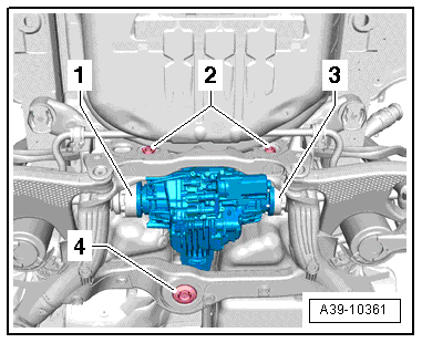
- Remove the left -1- and right -3- drive axles from the final drive.
- Loosen the bolts -2- approximately three turns.
- Remove the bolt -4-.
Lower the subframe -1- at the rear as follows:
- Remove the right rear bolt that connects the subframe to the body.
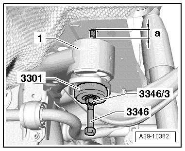
- Install the Bearing Installer - Control Arm -3346- with Control Arm Bearing Installer - Nut -3346/3- and Bearing from the Subframe Bushing Tool Kit -3301-.
- Then remove the left rear bolt that connects the subframe to the body.
- Lower the subframe to dimension -a- = 40 mm. While doing so counterhold the Bearing Installer - Control Arm -3346- and turn the Control Arm Bearing Installer - Nut - 3346/3- counter-clockwise.
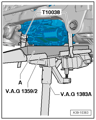
- Position the Engine and Gearbox Jack -VAS6931- with the Universal Transmission Support -VAG1359/2- and a corresponding rubber or hard foam mat -A- under the rear final drive.
 Caution
The rubber or hard foam mat is needed to protect the Clutch Valves on the rear final drive from getting damaged.
Use a Tensioning Strap -T10038- to secure the rear final drive from falling.
- Remove the two rear bolts -2- that connect the rear final drive to the subframe.
- A second technician must help with the next steps in removing the final drive.
- A second technician must now push the rear final drive in direction of -arrow- toward the right side of the vehicle.
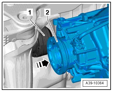
- Then guide the left drive axle -1- upward and out of the final drive flange shaft -2-.
- Guide the right drive axle out and tilt the final drive toward the rear and downward.
- Carefully lower the final drive together with the second technician. Pay attention to the subframe.
WARNING
- Do not raise or lower the vehicle when the Engine and Gearbox Jack -VAS6931- is underneath it.
- Do not leave the Engine and Gearbox Jack -VAS9631- under the vehicle longer than necessary.
Installing
Install in reverse order of removal. Note the following:
WARNING
Malfunctions on the rear final drive.
If the rear final drive was replaced, additional work is necessary. Refer to → Chapter "Additional Work after Replacing Rear Final Drive 0BE, 0BF".
- Carefully raise the rear final drive using the Engine and Gearbox Jack and, with a second technician, position it on the subframe in its installed position.
-A- = rubber or hard foam mat
Caution
The rubber or hard foam mat is needed to protect the Clutch Valves on the rear final drive from getting damaged.
Use a Tensioning Strap -T10038- to secure the rear final drive from falling.
- Install the right drive axle into the final drive flange shaft.
- A second technician must now push the rear final drive in direction of -arrow- toward the right side of the vehicle.
- Install the left drive axle -1- into the final drive flange shaft -2-.
- Install the bolts -2- that connect the rear final drive to the subframe hand-tight.
Note
For better illustration the Engine and Gearbox Jack -VAS6931- with the Universal Transmission Support -VAG1359/2- are not shown.
- Tighten the bolt -4- to the tightening specification and then the bolts -2- to the tightening specification. Refer to → Chapter "Overview - Final Drive 0BE, 0BF".
- Remove the Engine and Gearbox Jack -VAS6931- from under the final drive.
- Install the left -1- and right -3- drive axles. Refer to → Suspension, Wheels, Steering; Rep. Gr.42; Drive Axle; Drive Axle, Removing and Installing.
Attach the subframe -1- to the body in the rear as follows:
- First turn the Control Arm Bearing Installer - Nut -3346/3- clockwise until the subframe touches the body. While doing this, counterhold the Bearing Installer - Control Arm -3346-.
- Then install the left rear bolt that connects the subframe to the body and tighten it to the tightening specification. Refer to → Suspension, Wheels, Steering; Rep. Gr.42; Subframe; Overview - Subframe.
- The remove the Bearing Installer - Control Arm - 3346- and the right rear bolt for the subframe on the body and tighten to the tightening specification. Refer to → Suspension, Wheels, Steering; Rep. Gr.42; Subframe; Overview - Subframe.
- Attach the left drive axle heat shield -A- to the rear final drive -arrows-. Refer to → Chapter "Overview - Final Drive 0BE, 0BF".
- Install the wiring harness -3- to the final drive and subframe -items 5 through 7-.
- Connect the connectors -4 and 2-. Pay attention to the marks made during the removal, that identify the allocation to the Oil Pressure/Temperature Sensor and which connectors go to the Clutch Valves.
Caution
Risk of damaging the wiring harness.
Make sure the wiring harness -3- does not get pinched when installing the bracket -1- to the rear final drive.
- Position the bracket -1- on the final drive and tighten the bolts -arrows- to the tightening specification.
Note
- Allocation for the Oil Pressure/Temperature Sensor and Clutch Valves connectors:
- -1- = Oil Pressure/Temperature Sensor 2 -G640- Connector
- -2- = Oil Pressure/Temperature Sensor -G437- Connector
- -3- = All Wheel Drive Clutch Valve 2 -N446- Connector
- -4- = All Wheel Drive Clutch Valve -N445- Connector
- Install the driveshaft. Align the markings and follow the tightening sequence.
- Check the gear oil in rear final drive. Refer to → Chapter "Gear Oil, Checking Level, 0BE, 0BF".
- Check the ATF inside the rear final drive. Refer to → Chapter "ATF Level, Checking, 0BE, 0BF".
- Install the rear section of the exhaust system and align it so it is free of tension. Refer to → Rep. Gr.26; Exhaust Pipes/Mufflers; Overview - Muffler.
- If equipped, install the rear cross member. Refer to → Body Exterior; Rep. Gr.66; Underbody Panel; Overview - Underbody Panels.
- Install the rear wheels and tighten. Refer to → Suspension, Wheels, Steering; Rep. Gr.44; Wheels and Tires.
- If the rear final drive was replaced, additional work is necessary. Refer to → Chapter "Additional Work after Replacing Rear Final Drive 0BE, 0BF".
Additional Work after Replacing Rear Final Drive 0BE, 0BF
WARNING
Malfunctions on the rear final drive.
If the rear final drive was replaced, the following additional work is necessary.
- Bleed the hydraulic control module using the Vehicle Diagnostic Tester.
- Program the rear final drive on the All Wheel Drive Control Module -J492- use the Vehicle Diagnostic Tester → Vehicle diagnostic tester.
The additional work can only be performed when the rear final drive is replaced.
Procedure:
- Connect the Vehicle Diagnostic Tester and turn on the ignition.
- Select the function 22 - Rear Final Drive Replacing in the vehicle diagnostic tester under Guided Functions in the directory 22- All Wheel Drive (AWD) Electronics.
- Follow all the instructions given by the Vehicle Diagnostic Tester exactly.
The new rear final drive is "adapted" on the All Wheel Drive Control Module -J492- using the Vehicle Diagnostic Tester.
Note
A system check will take place when the function 22 - Rear Final Drive Replacing is complete. If malfunctions appear, then use "Guided Fault Finding" to correct them.
Tightening Specification
.png)
