Audi A6 Typ 4G: Airbag System
Component Location Overview - Airbag System
 Note
Note
The installation locations in the Sedan are illustrated.
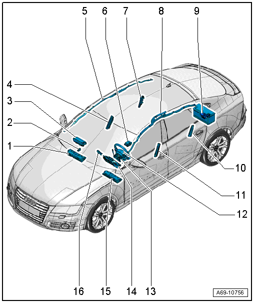
1 - Passenger Side Knee Airbag
- With Front Passenger Knee Airbag Igniter -N296-
- Market-specific
- Overview. Refer to → Chapter "Overview - Knee Airbag, Front Passenger Side".
2 - Front Passenger Airbag Deactivation Key Switch -E224-
- Not for North American market.
3 - Front Passenger Airbag with Front Passenger Airbag Igniter 1 -N131- and Front Passenger Airbag Release Valve Igniter -N491-
- Market-specific with Front Passenger Airbag Igniter 2 -N132-
- Overview. Refer to → Chapter "Overview - Front Passenger Airbag".
4 - Front Passenger Side Side Airbag with Front Passenger Thorax Airbag Igniter -N200-
- Overview. Refer to → Chapter "Overview - Front Side Airbag, Standard Seat/Sport Seat/Super Sport Seat".
5 - Front Passenger Head Curtain Airbag with Front Passenger Head Curtain Airbag Igniter -N252-
- Overview. Refer to → Chapter "Overview - Head Curtain Airbag".
6 - Airbag Control Module -J234-
- Overview. Refer to → Chapter "Overview - Airbag Control Module".
7 - Front Passenger Side Rear Side Airbag with Passenger Side Rear Thorax Airbag Igniter -N202-
- Equipment levels
- Overview. Refer to → Chapter "Overview - Rear Side Airbag".
8 - Driver Head Curtain Airbag with Driver Head Curtain Airbag Igniter -N251-
- Overview. Refer to → Chapter "Overview - Head Curtain Airbag".
9 - Battery Interrupt Igniter -N253-
- Overview. Refer to → Chapter "Overview - Battery Interrupt Igniter".
10 - Driver Side Rear Side Airbag with Driver Side Rear Thorax Airbag Igniter -N201-
- Equipment levels
- Overview. Refer to → Chapter "Overview - Rear Side Airbag".
11 - Driver Side Side Airbag with Driver Thorax Airbag Igniter -N199-
- Overview. Refer to → Chapter "Overview - Front Side Airbag, Standard Seat/Sport Seat/Super Sport Seat".
12 - Driver Side Airbag with Driver Airbag Igniter -N95- and Driver Airbag Release Valve Igniter -N490-
- Overview. Refer to → Chapter "Overview - Driver Side Airbag".
13 - Steering Column Electronics Control Module -J527- with Airbag Spiral Spring/Return Spring with Slip Ring -F138- and Steering Angle Sensor -G85-
- Removing and installing. Refer to → Electrical Equipment; Rep. Gr.94; Steering Column Switch Module; Steering Column Electronics Control ModuleJ527, Removing and Installing.
14 - Airbag Indicator Lamp -K75-
- Component location: in instrument cluster. Refer to → Electrical Equipment; Rep. Gr.90; Instrument Cluster; Overview - Instrument Cluster.
- Cannot be replaced separately
15 - Driver Side Knee Airbag
- With the Driver Knee Airbag Igniter -N295-
- Market-specific
- Overview. Refer to → Chapter "Overview - Knee Airbag, Driver Side".
16 - Front Passenger Airbag -Disabled- Indicator Lamp -K145-
- Integrated in the switch unit with the Start/Stop Mode Button -E693-, Parallel Parking Assistance Button -E581-, Parking Aid Button -E266-, Rear Spoiler Adjustment Switch -E127-, ASR/ESP Button -E256-; replace the switch unit if faulty. Refer to → Electrical Equipment; Rep. Gr.96; Controls; Overview - Instrument Panel Controls
Airbag Control Module
Overview - Airbag Control Module
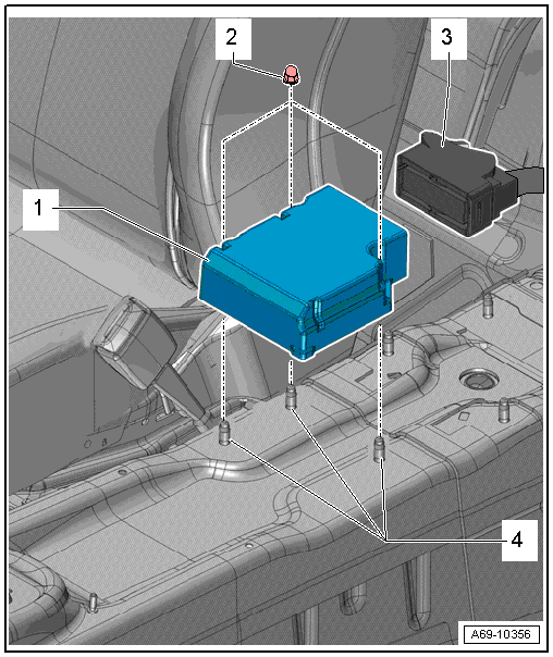
1 - Airbag Control Module -J234-
- Removing and installing. Refer to → Chapter "Airbag Control Module -J234-, Removing and Installing".
- Control module is grounded via the housing with the body.
2 - Nut
- 9 Nm
- Quantity: 3
- The thread must be paint and contaminant free, nut and ground bolts serve as ground connection for the control module
3 - Connector
4 - Threaded Pins
- The thread must be paint and contaminant free, nut and ground bolts serve as Ground (GND) connection for the control module
Airbag Control Module -J234-, Removing and Installing
Removing
 WARNING
Follow all Safety Precautions when working with pyrotechnic components. Refer to → Chapter "Pyrotechnic Components Safety Precautions".
- Disconnect the battery Ground (GND) cable with the ignition turned on. Refer to → Electrical Equipment; Rep. Gr.27; Battery; Battery, Disconnecting and Connecting.
- Remove the center console. Refer to → Chapter "Center Console, Removing and Installing".
- Remove the bracket for the center console. Refer to → Chapter "Center Console Bracket, Removing and Installing".
- Remove the rear air guide channel. Refer to → Heating, Ventilation and Air Conditioning; Rep. Gr.87; Air Guide; Air Distribution Channels, Removing and Installing.
- Fold up the floor covering over the airbag control module. Cut the floor covering along the perforation if necessary.
WARNING
Before handling pyrotechnic components (for example, disconnecting the connector), the person handling it must "discharge static electricity". This can be done by touching the door striker, for example.
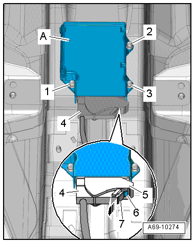
- Slide the retainer -7- on the connector in direction of -arrow-.
- Press the release button -6-, opening the retainer -5- on the connector and remove the connector -4-.
- Remove the nuts -1 through 3- and remove the airbag control module -A- from the threaded pins.
Installing
WARNING
- Follow all Safety Precautions when working with pyrotechnic components. Refer to → Chapter "Pyrotechnic Components Safety Precautions".
- Before handling pyrotechnic components (for example, connecting the connector), the person handling it must "discharge static electricity". This can be done by touching the door striker, for example.
Install in reverse order of removal. Note the following:
Note
Make sure the connectors are installed correctly and are secure.
WARNING
Ignition must be on when connecting battery. If pyrotechnic components (for example, airbag, belt tensioner) are not repaired correctly, they may deploy unintentionally after connecting battery. There must not be anyone inside the vehicle when connecting the battery.
DANGER!
When working on vehicles with the ignition already switched on or that are ready to drive there is a danger of the engine starting unexpectedly and of being poisoned by gas in enclosed areas. Risk of body parts and/or clothing being clamped or pulled.
Perform the following before switching on the ignition:
- Move the selector lever into P.
- Activate the parking brake
- Turn off the ignition.
- Open the hood
- Connect the charger, such as the Battery Charger -VAS5095A- to the jump start of the 12V vehicle electrical system.
- Turn on the ignition.
- Connect the battery GND cable with the ignition turned on. Refer to → Electrical Equipment; Rep. Gr.27; Battery; Battery, Disconnecting and Connecting.
Note
- If the Airbag Indicator Lamp -K75- signals a fault after installing, check the Diagnostic Trouble Code (DTC) memory, erase it and check it again. Refer to Vehicle Diagnostic Tester.
- Code the Airbag Control Module -J234- after replacing it. Refer to Vehicle Diagnostic Tester.
- The Airbag Control Module -J234- ground connection is achieved via the housing with the body.
Installation notes, for example tightening specifications, replacing components. Refer to → Chapter "Overview - Airbag Control Module".