Audi A6 Typ 4G: Lane Change Assistance
Overview - Lane Change Assistance
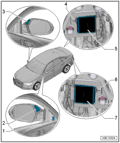
1 - Lane Change Assistance Button -E530-
- Removing and installing. Refer to → Chapter "Lane Change Assistance Button -E530-, Removing and Installing".
2 - Lane Change Assistance Warning Lamp In Driver Exterior Rearview Mirror -K233-
- Removing and installing. Refer to → Chapter "Lane Change Assistance Warning Lamp In Driver/Front Passenger Exterior Rearview Mirror -K233-/-K234-, Removing and Installing".
3 - Lane Change Assistance Warning Lamp In Front Passenger Exterior Rearview Mirror -K234-
- Removing and installing. Refer to → Chapter "Lane Change Assistance Warning Lamp In Driver/Front Passenger Exterior Rearview Mirror -K233-/-K234-, Removing and Installing".
4 - Screw
- 2 Nm
- Quantity: 3
5 - Lane Change Assistance Control Module -J769-
- Removing and installing. Refer to → Chapter "Lane Change Assistance Control Module -J769-/Lane Change Assistance Control Module 2 -J770-, Removing and Installing".
- Calibrating. Refer to → Chapter "Lane Change Assistance, Calibrating".
6 - Screw
- 2 Nm
- Quantity: 3
7 - Lane Change Assistance Control Module 2 -J770-
- Removing and installing. Refer to → Chapter "Lane Change Assistance Control Module -J769-/Lane Change Assistance Control Module 2 -J770-, Removing and Installing".
- Calibrating. Refer to → Chapter "Lane Change Assistance, Calibrating".
Lane Change Assistance Button -E530-, Removing and Installing
Removing
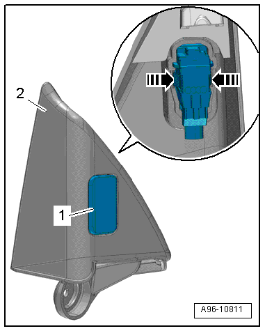
- Remove the inner cover. Refer to → Body Interior; Rep. Gr.70; Front Door Trim Panels; Overview - Front Door Trim Panel.
- Release the tabs in direction of -arrows- and remove the lane change assistance button -1- from the cover -2-.
Installing
Install in reverse order of removal.
Lane Change Assistance Warning Lamp In Driver/Front Passenger Exterior Rearview Mirror -K233-/-K234-, Removing and Installing
Removing
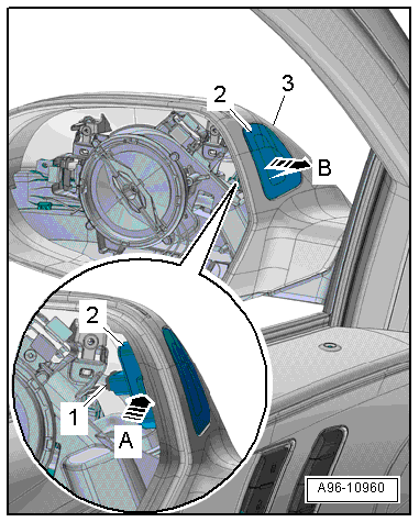
- Remove the mirror glass. Refer to → Body Exterior; Rep. Gr.66; Exterior Rearview Mirror; Mirror Glass, Removing and Installing.
- Disconnect the connector -1-.
- Open the tab in direction of -arrow A- and remove the warning lamp -2- from the exterior rearview mirror housing -3- in direction of -arrow B-.
Installing
Install in reverse order of removal. Note the following:
 Note
Note
If an LED is faulty, the entire lane change assistance warning lamp in the exterior rearview mirror must be replaced.
Lane Change Assistance Control Module -J769-/Lane Change Assistance Control Module 2 -J770-, Removing and Installing
Removing
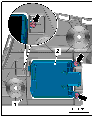
- Remove the bumper cover exterior mount. Refer to → Body Exterior; Rep. Gr.63; Rear Bumper; Attachments, Removing and Installing.
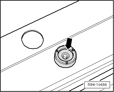
- Remove the bolts -arrows-.
- Remove the lane change assistance control module -2- from the mount -1-.
Installing
Install in reverse order of removal. Note the following:
- Calibrate the Lane Change Assistance Control Module -J769-/Lane Change Assistance Control Module 2 -J770-. Refer to → Chapter "Lane Change Assistance, Calibrating".
Lane Change Assistance, Calibrating
Special tools and workshop equipment required
- Calibration Tool -VAS6350-
Conditions
- The Calibrate the Lane Change Assistance Control Module -J769-/Lane Change Assistance Control Module 2 -J770- must be calibrated in the "Guided Fault Finding" or "Guided Functions" operating mode under the following conditions using the Vehicle Diagnostic Tester:
- Lane Change Assistance Control Module -J769- or Lane Change Assistance Control Module 2 -J770- was replaced.
- The rear bumper cover was damaged.
- The rear bumper cover was removed and installed.
- The DTC "no or incorrect basic setting/adaptation" is stored in the DTC memory.
Preparing for Calibration
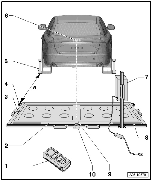
1 - Calibration Tool - Spacing Laser -VAS6350/2-
- For distance measurement
- For information on usage. Refer to the Calibration Tool -VAS6350- Operating Instructions
2 - Calibration Tool -VAS6350-
3 - Level
- On the Calibration Tool -VAS6350-
- To check the horizontal position of the Calibration Tool -VAS6350-
4 - Catch Bracket
- To mount the Calibration Tool - Spacing Laser -VAS6350/2- for the distance measurement
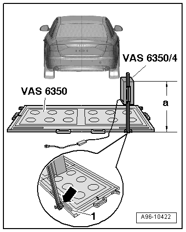
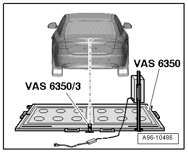
- Distance to the Calibration Tool - Wheel Center Mounting -VAS6350/1- on the rear wheels: dimension -a- = 1700 +- 2 mm
5 - Calibration Tool - Wheel Center Mounting -VAS6350/1-
- With wheel bolt adapter and measuring paddle
6 - Brand Emblem
- The laser point is aligned on the center of the brand emblem
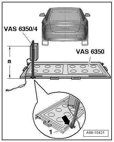
7 - Calibration Tool - Lane Change Calibration Tool -VAS6350/4-
- Is moved from one side of measuring field to the other during calibration
- When installed correctly, vehicle electrical system voltage line must be connected at bottom left of calibration tool (as seen in direction of travel)
8 - Measurement Scale
- For positioning the Calibration Tool - Lane Change Calibration Tool -VAS6350/4-
9 - Calibration Tool - Linear Laser -VAS6350/3-
- With "laser eye protection"
- On the Calibration Tool -VAS6350-
- To turn on and off. Refer to the Calibration Tool -VAS6350- Operating Instructions
10 - Plastic Foot
- Quantity: 3
- Can be adjusted for adjusting the horizontal position of the Calibration Tool -VAS6350-
Procedure
- Move the vehicle onto a solid, flat surface.
- Set the parking brake - the vehicle must not move during the measuring.
- Place the front wheels in a straight-ahead position - steering wheel in 0 position.
- Connect the Vehicle Diagnostic Tester.
Note
If a malfunction message appears in the display using the Vehicle Diagnostic Tester.
- Turn on the ignition.
- Remove the label with the metal foil from the bumper cover, if necessary.
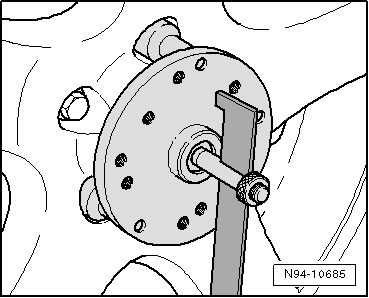
- Secure three suitable wheel bolt adapters for the wheel bolts on each Calibration Tool - Wheel Center Mounting -VAS6350/1-.
- Insert the measuring paddle on both Calibration Tool - Wheel Center Mounting -VAS6350/1- and secure it with the locking nut.
- Place the Calibration Tool - Wheel Center Mounting -VAS6350/1- onto the wheel bolts on both rear wheels.
- The wheel center sensor rotation center must be in wheel rotation center.
Note
Place the Calibration Tool - Wheel Center Mounting -VAS6350/1- on wheels so that "anti-theft wheel bolts" are not connected with wheel center mounting.
- Adjust the measuring paddle with aid of lock nuts so that they move freely just above the floor.
- The measuring paddles must move easily.
- The measuring paddles must be vertical.
- Position the Calibration Tool -VAS6350- at distance -a- to the rear wheels.
- Dimension -a- = 1,700 mm
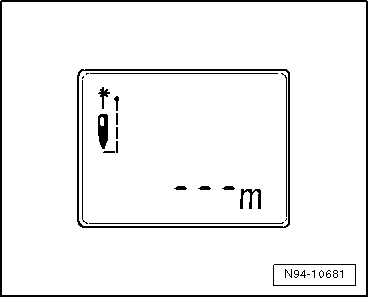
- Switch on the Calibration Tool - Spacing Laser -VAS6350/2- with the ON button.
Display on the Calibration Tool - Spacing Laser -VAS6350/2-:
- "- - - m"
Note
The laser is switched on at same time.
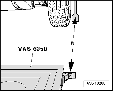
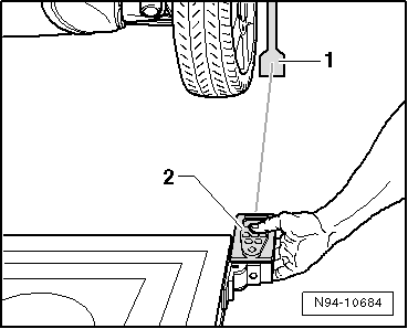
- For distance measurement, hold the Calibration Tool - Spacing Laser -VAS6350/2--item 2- flush to the right stop bracket as illustrated.
- The Calibration Tool - Spacing Laser -VAS6350/2- must lie firmly against the catch bracket.
- Make sure the "laser beam" for the distance measurement contacts the enlarged lower part on the paddle -1-.
If this is not the case, measure paddle height must be corrected using locking nuts on Calibration Tool - Wheel Center Mounting -VAS6350/1-.
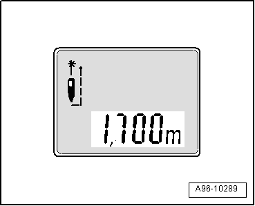
- Briefly press ON button for distance measurement.
Display on the Calibration Tool - Spacing Laser -VAS6350/2-:
- "1.700 m" (specified value: 1700 +- 2 mm).
- Repeat the measuring procedure from the left catch bracket to the left rear wheel
- The distance value must be the same on both sides.
If both measured values are not the same, adjust the Calibration Tool -VAS6350- accordingly.
Performing Calibration
Vehicle Diagnostic Tester is attached.
- Select the Diagnostic mode and start the diagnostics.
- Select the tab test plan.
- Select select individual tests and choose the following sequence.
- Body
- Electrical Equipment
- 01 - OBD-capable systems
- 3C - Lane change assistance control module - J769
- 3C - Lane change assistance control module, functions
- 3C - Calibration
From here using the Vehicle Diagnostic Tester advances the calibration procedure forward.
Note
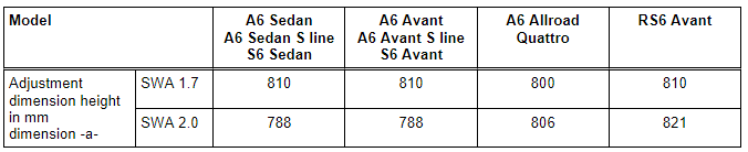
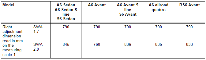
- The following information clarifies which version of the lane change assist is installed (version SWA1.7).
- This information for adjusting the calibration device is important for later steps in the procedure to avoid malfunctions.
- Secure the right rear Calibration Tool - Lane Change Calibration Tool -VAS6350/4- to the Calibration Tool -VAS6350- mount.
- When installed correctly, vehicle electrical system voltage line must be connected at bottom left of calibration device (as seen in direction of travel).
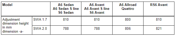
Dimension -a- is measured from the upper edge of calibration device to the floor.
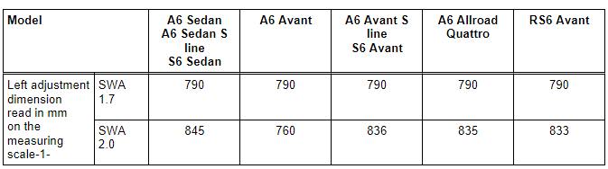
- The indicator on the base of the Calibration Tool - Lane Change Calibration Tool -VAS6350/4- must align with adjustment dimension on the measuring scale -1- on measuring field -arrow-.
- Connect the Calibration Tool - Lane Change Calibration Tool -VAS6350/4- to the vehicle electrical system voltage.
- Bring Calibration Tool -VAS6350- into horizontal position by turning the plastic feet.
- Observe the bubble level (sight glass) on the Calibration Tool -VAS6350--arrow-.
- Turn on the Calibration Tool - Linear Laser -VAS6350/3- on the Calibration Tool -VAS6350-.
- Wear "laser protective eyewear".
- Align the Calibration Tool -VAS6350- so that the Calibration Tool - Linear Laser -VAS6350/3- strikes the center of the brand emblem on the rear lid.
- Check left and right distance between catch bracket on Calibration Tool -VAS6350- and measuring paddle -1- on wheel mountings again.
- Specified value: 1700 +- 2 mm
Calibration Procedure
The following should not occur during the calibration procedure:
- No metal reflectors may be located within a two m radius of the calibration device (for example, tool carts, metal cabinets).
- Vehicle doors must not be opened or closed.
- People should not sit in the vehicle.
- People must not go between the vehicle and the Calibration Tool - Lane Change Calibration Tool -VAS6350/4-.
Procedure
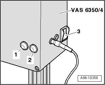
- Turn on the Calibration Tool - Lane Change Calibration Tool -VAS6350/4- on the voltage switch -3-.
- The green LED -1- must light up.
Note
If the red LED -2- illuminates: Check the Calibration Tool - Lane Change Calibration Tool -VAS6350/4-.
- Follow the instructions in the Vehicle Diagnostic Tester display.
During the course of the program, a request is made to switch the Calibration Tool - Lane Change Calibration Tool -VAS6350/4- from the right to the left side of the Calibration Tool -VAS6350-.
- Turn off the Calibration Tool - Lane Change Calibration Tool -VAS6350/4- and remove the calibration tool.
- When installed correctly, vehicle electrical system voltage line must be connected at bottom left of calibration device (as seen in direction of travel).
Dimension -a- is measured from the upper edge of calibration device to the floor.
- The indicator on the base of the Calibration Tool - Lane Change Calibration Tool -VAS6350/4- must align with adjustment dimension on the measuring scale -1- on measuring field -arrow-.
- Turn on the Calibration Tool - Lane Change Calibration Tool -VAS6350/4- on the voltage switch -3-.
- The green LED -1- must light up.
- Follow the instructions in the Vehicle Diagnostic Tester display.
- After calibrating the lane change assistance successfully, end "calibration", switch off the ignition and disconnect the diagnostic connector.
