Audi A6 Typ 4G: Active Steering Safety Lock (Locking Magnet), Removing and Installing
Special tools and workshop equipment required
- Torque Wrench 1783 - 2-10Nm -VAG1783-
- Vehicle Diagnostic Tester
 WARNING
Note the following before working on the steering column:
- Components of the steering are safety related!
- Only specially trained technician should work on the steering system for reasons of safety. Incorrect work could result in serious crashes.
- Route the electrical wiring harnesses exactly the way they were before removal.
- Secure the electrical wiring harnesses exactly the way they were before removal.
Removing
 Note
Note
The steering wheel cannot be turned and the front wheels cannot be moved out of the straight ahead position when the adjusting element is removed. Otherwise the position of the steering wheel may be incorrect after the work is completed. Follow all the rule for cleanliness when performing the following work.
- Turn the steering wheel into the straight-ahead position (the wheels on the front and rear axle must now line up) and lock the steering wheel lock in the straight-ahead position.
- Turn off the ignition.
- Remove the driver side instrument panel cover -2-. Refer to → Body Interior; Rep. Gr.68; Storage Compartments and Covers; Driver Side Instrument Panel Cover, Removing and Installing.
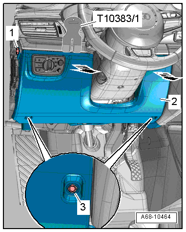
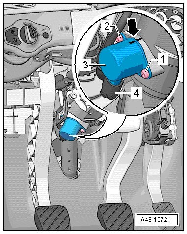
- Mark the installed position and the position of the Active Steering Safety Lock Actuator -F437- (dynamic steering) -arrow- (needed for installation later).
- Disconnect the connector -4- from the actuator -3-.
- Remove any paint still on the bolt heads -1 and 2-.
- Remove the bolts -1 and 2- and the actuator -3- from the steering column.
- To remove the bolts -1 and 2-, use the socket supplied in the new actuator repair kit.
Installing
Install in reverse order of removal. Note the following:
- After replacing the Active Steering Safety Lock Actuator -F437- (dynamic steering), update the software for the Active Steering Control Module -J792- by starting the corresponding program on the Vehicle Diagnostic Tester in Guided Functions.
- If a new Active Steering Safety Lock Actuator -F437- (dynamic steering) is installed, transfer the marking from the old one to the new one.
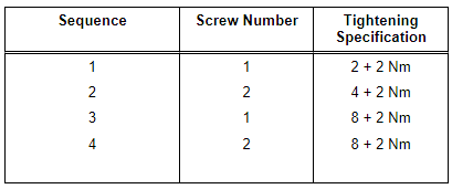
- Install the new actuator as shown in the following table and secure it with both new bolts -1 and 2- (use the supplied tool).
Tightening Sequence
- Connect the connector to the actuator.
- Erase the Diagnostic Trouble Code (DTC) memory.
- Perform an initializing drive - turn the vehicle 45º to the left/right from the straight-ahead position.
Functional Check
Check the function of the steering during the road test and a fenced off area.
- Operating force
- Reset
- Play
- Noise
- Indicator lamp
- Read the DTC memory after the road test. There must be no faults in the DTC memory.
Steering Intermediate Shaft, Removing and Installing
Special tools and workshop equipment required
- Torque Wrench 1331 5-50Nm -VAG1331-
Removing
- Straighten the wheels.
- Position the steering wheel as far down as possible using the full range of the steering column adjuster.
- Move the driver seat forward to the stop.
- Turn off the ignition and remove the key.
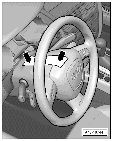
- Turn the steering wheel so that the wheels are in the straight-ahead position and then tape it secure -arrow- so that it cannot turn.
Note
- Be sure to use tape that will not leave behind any residue when it is removed.
- Be careful not to turn the steering wheel during the repair because the Airbag Spiral Spring/Return Spring with Slip Ring -F138- can become damaged.
- Remove the driver side instrument panel cover. Refer to → Body Interior; Rep. Gr.68; Storage Compartments and Covers; Driver Side Instrument Panel Cover, Removing and Installing.
WARNING
Danger of getting burned by the exhaust system depending on the engine installed.
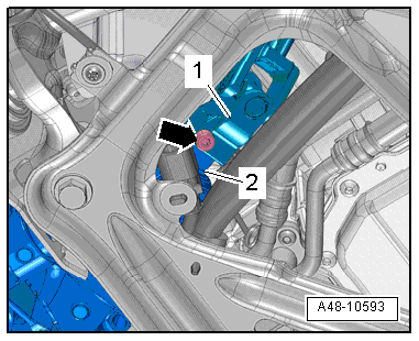
- Remove the bolt -arrow-.
- Remove the steering intermediate shaft -1- from the steering gear -2-.
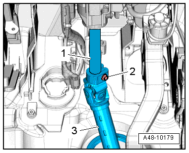
- Remove the bolt -2- and remove the steering intermediate shaft -3- from the steering column -1-.
- Remove the rear noise insulation. Refer to → Body Exterior; Rep. Gr.66; Noise Insulation; Noise Insulation, Removing and Installing.
- Fold the floor covering carefully to the rear.
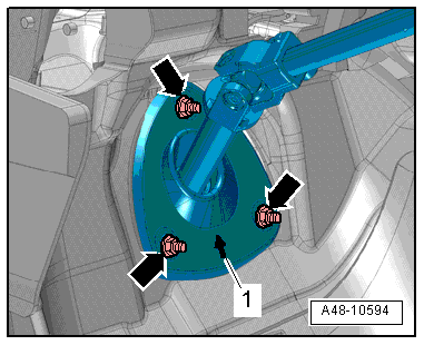
- Remove the nuts -arrows-.
- Remove the sealing boot from the body.
- Remove the steering intermediate shaft toward the passenger compartment.
Installing
Install in reverse order of removal. Note the following:
Note
The threaded hole for the bolt must always be cleaned (for example, using a thread tap).
- Make sure the rubber grommet fits correctly on the sealing boot before installing the steering intermediate shaft.
- The arrow -1- point up in the installed position.
- Move the steering intermediate shaft into its installed position from inside the passenger compartment.
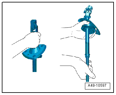
- The steering shaft must be held over the sealing boot on the upper steel shaft when being transported as illustrated.
- Hold the steering shaft with one hand under the sealing boot on the sealing plug and by the lower steel shaft with the second hand as illustrated.
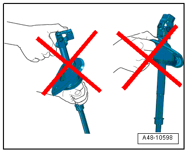
 Caution
Danger of causing damage to the steering shaft and the sealing boot.
- Do not carry the steering shaft by the steering shaft.
- Do not remove the sealing boot from the steering shaft.
- Do not overbend the joints past the stop.
- The mount the steering intermediate shaft -1- all the way onto the steering gear -2- and tighten the bolt -arrow-.
WARNING
Pull on the steering intermediate shaft -1- to make sure it is secure when the bolt -arrow- is installed. Then tighten the bolt -arrow-.
Install in reverse order of removal.
Electronic Steering Column Lock Control Module -J764-, Removing and Installing
Special tools and workshop equipment required
- Torque Wrench 1783 - 2-10Nm -VAG1783-
- Vehicle Diagnostic Tester
Removing
WARNING
Note the following before removing the steering column:
Create a sketch showing the:
- Routing of the electrical wiring harnesses,
- Securing the electrical wiring harnesses,
- Cable tie locations.
This especially applies to the wiring harness to the Electronic Steering Column Lock Control Module -J764-.
Note the following before installing the steering column:
- Route the electrical wiring harnesses exactly the way they were before removal.
- Secure the electrical wiring harnesses exactly the way they were before removal.
- Install all the cable ties that were loosened or cut in the same locations when installing the steering column.
- Make sure the wiring harness to the Electronic Steering Column Lock Control Module -J764- is not pinched and does not come into contact with sharp edges when adjusting the steering column.
- If the control module is being replaced, then select "replace" control module on the Vehicle Diagnostic Tester in Guided Functions.
- Remove the steering column. Refer to → Chapter "Steering Column, Removing and Installing".
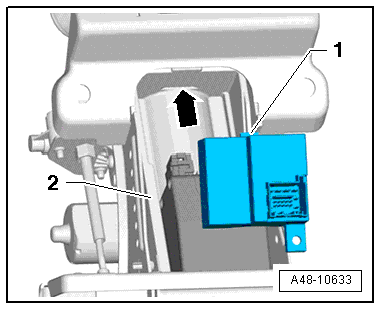
- Remove the bolt -1- and the Electronic Steering Column Lock Control Module -J764--2-.
WARNING
After removing the control module, make sure no dirt or foreign objects enter the steering column.
Installing
Install in reverse order of removal. Note the following:
- If only the Electronic Steering Column Lock Control Module -J764- was replaced, use the previously used control module bolt.
- If the steering column was replaced, remove the protective cover and use the bolt in the new steering column for the Electronic Steering Column Lock Control Module -J764-.
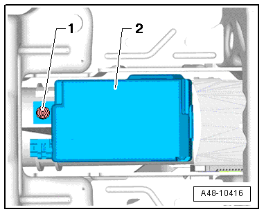
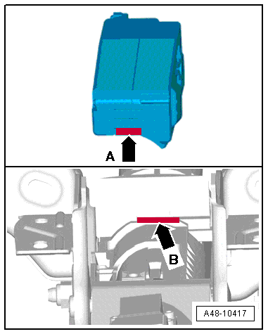
- Insert the Electronic Steering Column Lock Control Module -J764- with the tab -arrow A- into the groove -arrow B- in the steering column and then push on the Electronic Steering Column Lock Control Module -J764- by hand.
- Once the Electronic Steering Column Lock Control Module -J764--2- is touching the entire surface of the steering column, install the bolt -1- and tighten it.
- Install the steering column. Refer to → Chapter "Steering Column, Removing and Installing".
- If the Steering Angle Sensor -G85- indicator lamp in the instrument cluster comes on, correct the fault and, if necessary, perform a basic setting on the dynamic steering. Refer to → Chapter "Dynamic Steering Basic Setting".
Power Adjustable Steering Column Control Module -J866-, Removing and Installing
Special tools and workshop equipment required
- Torque Wrench 1410 -VAG1410-
- Vehicle Diagnostic Tester
Removing
- If the control module is being replaced, then select "replace" control module on the Vehicle Diagnostic Tester in Guided Functions.
- Remove the steering column. Refer to → Chapter "Steering Column, Removing and Installing".
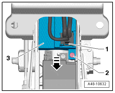
- Disconnect the connector -1-.
- Remove the bolt -2-.
- Slightly lift the Power Adjustable Steering Column Control Module -J866--3- and remove it from the steering column in direction of -arrow-.
Installing
Install in reverse order of removal. Note the following:
- Install the Power Adjustable Steering Column Control Module -J866- with the pin -1- into the groove -arrow- on the steering column -2-.
- Perform a basic setting on the steering column if the Power Adjustable Steering Column Control Module -J866- was replaced.
- Connect the Vehicle Diagnostic Tester and proceed with a vehicle-specific entry in Guided Functions.
- Select the program in Guided Functions under the address "09 - electronic central electric".
- Follow the prompts on the screen.