Audi A6 Typ 4G: Axle Alignment Specified Values
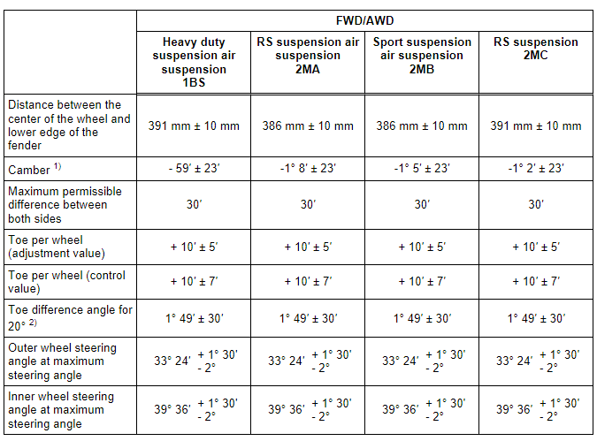
Axle Alignment Specified Values, Sportback Front Axle
 Note
Note
The specified values apply to all engine versions.
.png)
1) On RHD vehicles, the camber must be determined based on the distance between the wheel center and the lower edge of the fender.
2) Wheel stop on outer wheel is reduced by this amount. It can also be indicated negatively in alignment computer, depending on manufacturer.
1) On RHD vehicles, the camber must be determined based on the distance between the wheel center and the lower edge of the fender.
2) Wheel stop on outer wheel is reduced by this amount. It can also be indicated negatively in alignment computer, depending on manufacturer.
Additional Vehicle Data for Vehicles with FWD and AWD:
This additional vehicle data only serves for a faster diagnosis in the case of accidents.
Table. Refer to → Chapter "Suspension".
Axle Alignment Specified Values, Sportback Rear Axle
Note
The specified values apply to all engine versions.
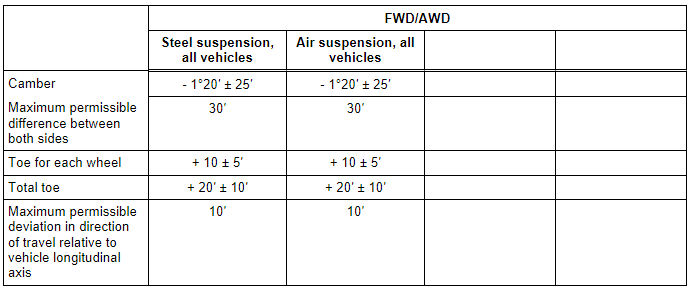
Additional Vehicle Data for Vehicles with FWD and AWD:
This additional vehicle data only serves for a faster diagnosis in the case of accidents.
Table. Refer to → Chapter "Suspension".
Axle Alignment Specified Values, Sedan/Avant Front Axle
Note
The specified values apply to all engine versions.
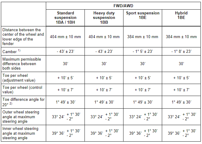
1) On RHD vehicles, the camber must be determined based on the distance between the wheel center and the lower edge of the fender.
2) Wheel stop on outer wheel is reduced by this amount. It can also be indicated negatively in alignment computer, depending on manufacturer.
.png)
1) On RHD vehicles, the camber must be determined based on the distance between the wheel center and the lower edge of the fender.
2) Wheel stop on outer wheel is reduced by this amount. It can also be indicated negatively in alignment computer, depending on manufacturer.
.png)
1) On RHD vehicles, the camber must be determined based on the distance between the wheel center and the lower edge of the fender.
2) Wheel stop on outer wheel is reduced by this amount. It can also be indicated negatively in alignment computer, depending on manufacturer.
Additional Vehicle Data for Vehicles with FWD and AWD:
This additional vehicle data only serves for a faster diagnosis in the case of accidents.
Table. Refer to → Chapter "Suspension".
Axle Alignment Specified Values, Sedan/Avant Rear Axle
Note
The specified values apply to all engine versions.
.png)
Additional Vehicle Data for Vehicles with FWD and AWD:
This additional vehicle data only serves for a faster diagnosis in the case of accidents.
Table. Refer to → Chapter "Suspension".
Axle Alignment Procedure
Note
- Vehicle must only be measured in the control position or curb weight position. Refer to → Chapter " Test Prerequisites"!
- Check which suspension is installed in the vehicle. This information can be found on the vehicle data plate. Refer to → Chapter "Production Control Number (PR number) Explanation".
Observe the Following Work Sequence!
1 - Drive the vehicle onto the alignment rack without tension. Move the vehicle back and forth if necessary to relieve any tension on the axle components.
2 - The steering wheel must be "evened out" into the center position before beginning the measuring and adjusting. Use Steering Wheel Scales -VAS 6458- for this.
3 - Perform wheel run-out compensation. Refer to → Chapter "Wheel Run-Out Compensation".
4 - Check the maximum steering angle. Refer to → Chapter "Maximum Steering Angle, Checking".
5 - Check rear axle camber and adjust if necessary. Refer to → Chapter "Rear Axle Camber, Adjusting".
6 - Check rear axle toe and adjust if necessary. Refer to → Chapter "Rear Axle Toe, Adjusting".
7 - Check front axle camber and adjust if necessary. Refer to → Chapter "Front Axle Camber, Adjusting".
8 - Check the front axle toe and adjust if necessary. Refer to → Chapter "Front Axle Toe, Adjusting".
Note
If the adjustments on the suspension were changed, then perform a zero compensation on the Steering Angle Sensor -G85- with the Vehicle Diagnostic Tester.
Perform a basic setting on the dynamic steering, if equipped, if adjustments on the front and/or rear axles were changed. Refer to → Chapter "Dynamic Steering Basic Setting".
If the rear axle setting was corrected, then the ACC sensors must be adjusted on vehicles with ACC (refer to → Chapter "Adaptive Cruise Control (ACC), Calibrating"), the lane assist must be calibrated on vehicles with lane assist (refer to → Chapter "Driver Assistance Systems Front Camera, Calibrating"), the night vision system must be adjusted/calibrated on vehicles with infrared system (refer to → Chapter "Infrared System, Calibrating") and the rearview camera must be calibrated on vehicles with a rearview camera. Refer to → Communication; Rep. Gr.91; Rearview Camera System; Rearview Camera System, Aligning and Calibrating.
Evaluating Need for Axle Alignment
- Vehicle shows handling problems.
- Involved in an accident.
- Axle components have been removed or replaced.
- Tire wear patterns are uneven.
.png)
1) Even if the subframe was secured with the Subframe Locating Pins -T40242-, an axle alignment may be necessary. Perform a road test. Refer to → Chapter "Subframe, Securing, FWD".
Production Control Number (PR number) Explanation
The vehicle data plate documents which front/rear axle or tire pressure monitoring system is installed using the corresponding PR numbers.
There is a vehicle data label in the spare wheel well and also one in the customer Maintenance booklet.
Front/Rear Axle
The front/rear axle PR No. is in illustration -A and B-.
- The front axle PR number is Item -A-.
- Item -B- shows PR number for rear axle
Use the PR number to find the correct shock absorber combination in the Parts Catalog.
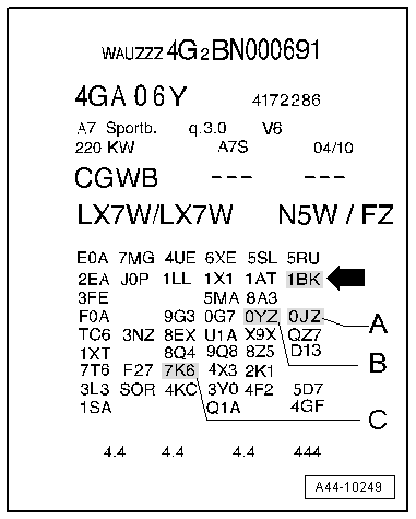
Suspension Versions
The suspension version PR No. is in illustration -arrow-
In this example the vehicle has standard suspension 1BK installed.
1BA / 1BH= Standard suspension
1BE = Sport suspension
1BB/1BR = Heavy duty suspension
1BK = Standard suspension air suspension
1BS = Heavy duty suspension air suspension
1BV = Sport suspension S line
1BY = allroad
2MA = RS suspension air suspension
2MB = Sport suspension air suspension
2MC = RS suspension
Tire Pressure Monitoring System/Tire Pressure Monitoring System Display
The tire pressure monitoring system PR number can be found in ELSA in Vehicle Individual under "Vehicle Data".
7K0 = Without tire pressure monitoring system
7K6 = Tire pressure monitoring system display
7K8 = Tire pressure monitoring system, frequency 315 MHz Basis
Driver Assist System
The driver assist system PR number can be found in ELSA in Vehicle Individual under "Vehicle Data".
1N7, 1N8 = dynamic steering
7Y2 = Lane assist
7Y3 = Lane change assistance and lane assist
7Y4 = Lane assist (Heading Control Assist)
8T4 = Adaptive cruise control (ACC)
8T5 = Adaptive cruise control plus cruise control
9R1 = Night vision system
