Audi A6 Typ 4G: Front Axle Camber, Adjusting
Camber cannot be adjusted.
Camber can be centered evenly within specified tolerance range by shifting subframe.
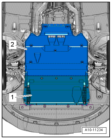
- Remove the noise insulation -1 and 2-. Refer to → Body Exterior; Rep. Gr.66; Noise Insulation; Noise Insulation, Removing and Installing.
- If installed: remove the front lower longitudinal member at the left and right. Refer to → Body Exterior; Rep. Gr.63; Front Bumper; Overview - Impact Member.
- Remove the left and right wheel spoiler. Refer to → Body Exterior; Rep. Gr.66; Wheel Housing Liner; Overview - Front Wheel Housing Liner.
- Loosen the inner wheel housing liners at the left and right (refer to → Body Exterior; Rep. Gr.66; Wheel Housing Liner; Front Wheel Housing Liner, Removing and Installing and push them outward.
- Remove the heat shield upper section. Refer to → Chapter "Subframe Heatshield, Removing and Installing".
 WARNING
Danger of accident due to a loose subframe.
Do not completely remove the subframe bolts.
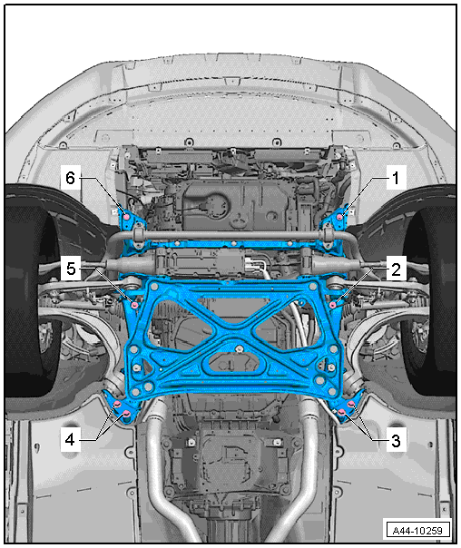
- Loosen the subframe bolts -1 through 6- two turns at the left and right diagonally and in steps.
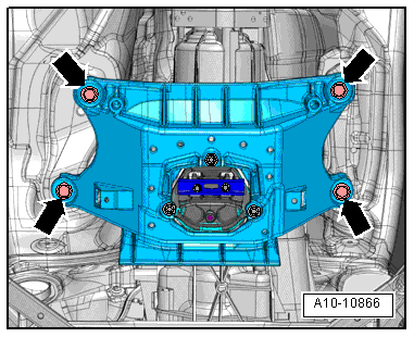
- Loosen the bolts -arrows- for the tunnel cross member. Refer to → Rep. Gr.34; Subframe Mount; Overview - Subframe Mount or → Rep. Gr.37; Subframe Mount; Overview - Subframe Mount.
 Note
Note
If the subframe is moved, the front of the vehicle must be lifted at the jack points using an axle lift.
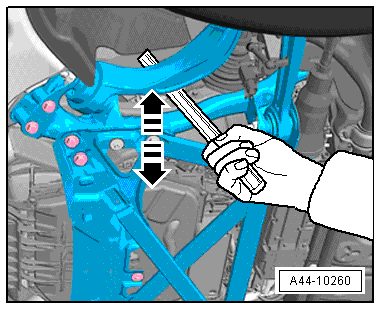
- Using a plastic-coated tire iron, slide the subframe with the engine mount and stabilizer bar in the appropriate location -arrows-.
- Push in the center of the subframe near the lower control arm between the subframe and the body longitudinal member.
If you do not have a plastic-coated tire iron, wrap a standard tire iron in adhesive tape.
- The vehicle must be bounced several times at the front axle before checking the camber values.
WARNING
Do not damage any parts!
Axle alignment specified values. Refer to → Chapter "Axle Alignment Specified Values".
- Remove the subframe bolts one after the other and replace them.
- Tighten the bolts -1 through 6-. Refer to → Chapter "Overview - Subframe".
- Tighten the bolts -arrows- for the tunnel cross member. Refer to → Rep. Gr.34; Subframe Mount; Overview - Subframe Mount or → Rep. Gr.37; Subframe Mount; Overview - Subframe Mount.
- Check the camber value one more time. Refer to → Chapter "Axle Alignment Specified Values".
 Caution
Every time camber is corrected, axle alignment values should be checked.
Rear Axle Camber, Adjusting
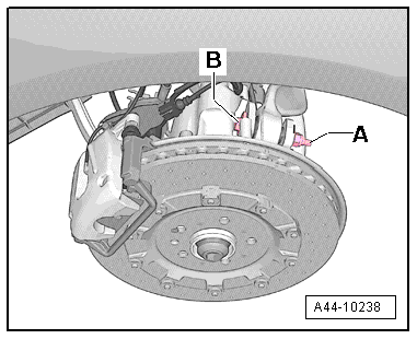
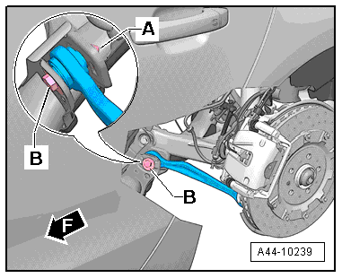
- Remove the nut -A- of threaded connection of wheel bearing housing/control arm, and screw on new nut until stop.
- Adjust the camber by rotating the adjusting bolt -B-. To turn the adjusting screw -B-, turn the hex head at the "top of the screw".
Axle alignment specified values. Refer to → Chapter "Axle Alignment Specified Values".
Note
- The maximum adjustment range is 135º to left or right of center position.
- Do not rotate the adjusting bolt -B- further once the end position has been reached or the components will be damaged.
- For a better illustration, camber adjustment is shown with wheel removed.
- Tighten nut -A--Item 13-.
- After tightening nut -A-, check camber value once more. Refer to → Chapter "Axle Alignment Specified Values".
Rear Axle Toe, Adjusting
Special tools and workshop equipment required
- Track Rod Tool Insert -T40183-
- No illustration, commercially available pawl with fine gear
- Remove the nut -A- of threaded connection tie rod/subframe, and screw on new nut until stop.
- Adjust toe by turning eccentric bolt -B-.
Axle alignment specified values. Refer to → Chapter "Axle Alignment Specified Values".
- Tighten the nut -A- using the Track Rod Tool Insert -T40183--Item 4-.
- After tightening nut -A-, check toe value once more. Refer to → Chapter "Axle Alignment Specified Values".
Note
- The maximum adjustment range is 90º to left or right of center position.
- The geometric drive axle is automatically changed when individual toe settings are changed.
Front Axle Toe, Adjusting
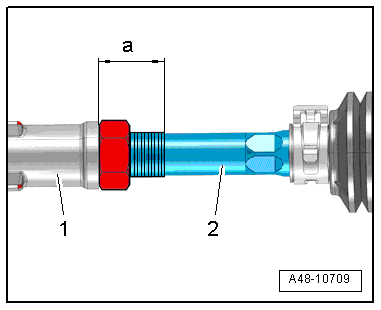
- Measure the dimension -a- between the tie rod head -1- and the left and right tie rod -2- and make a note of the value. Dimension -a- should be the same before and after adjusting on the left and right.
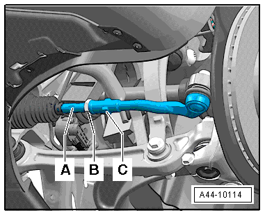
- Loosen lock nut -B-.
Note
Counterhold the tie rod end -C- when loosening or tightening the lock nut -B-.
- Adjust toe on left and right-hand wheels at hex -A-.
Be Sure That Boot Is Not Twisted After Turning Tie Rods.
Twisted boots wear out quickly.
- Tighten lock nut -B-, -Item 11- and check toe-in value again.
After tightening lock nut -B- it is possible that the value deviates slightly.
If the measured toe nevertheless lies within the tolerance, the adjustment is correct.
Wheel Run-Out Compensation
A correct toe-in adjustment will not be possible without performing lateral run-out compensation!
The lateral run-out of the wheel must be compensated for. Otherwise, measurement will result in false readings.
Permissible axial run-out of the wheel rims can exceed the specified toe setting tolerance. If compensation for wheel run-out is not performed, it will not be possible to obtain a correct toe-in adjustment.
Follow the operating instructions provided by the manufacturer of the alignment equipment.
Maximum Steering Angle, Checking
The wheel alignment computer determines the maximum steering angle.
- If the maximum steering angle has been determined on the alignment equipment, so that the value is not within the tolerance, then check for damage or deformations to the steering and suspension components and inspect the symmetry of the ties rod. In this case, shorten the "longer" tie rod end (install it deeper into the tie rod) and replace any damaged components.
- If a steering wheel fault is determined on the alignment equipment when setting the center position of the steering, then check the steering and suspension for damage or deformations and replace any damaged components. Check the tie rod symmetry as well.
- Measure dimension -a- on the "shorter" tie rod head. Shorten the "longer" tie rod head to the same dimension. To do this, install the tie rod head -1- deeper on the tie rod -2-.
Dimension -a- of right tie rod end = dimension -a- of left tie rod end; maximum permissible difference between right and left < 2.5 mm.
- When the steering wheel returns to its center position, let the steering wheel "come to its center" using even movements.
Axle Alignment Control Position on Vehicles with Air Suspension, Checking
Axle Alignment Control Position, Checking
Before performing an axle alignment on a vehicle with air suspension, check the curb weight or control position and adapt it again if necessary.
- Start the "axle alignment" using the Vehicle Diagnostic Tester in Guided Functions.
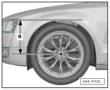
Determining the Height Dimension -a-
Height dimension -a- is the measurement in mm between center of wheel and lower edge of fender.
- Determine dimension -a- between the center of the wheel and the lower edge of the fender/wheel housing as illustrated.
Height Dimensions Overview
Sportback
.png)
Sedan/Avant
.png)
