Audi A6 Typ 4G: Adaptive Cruise Control (ACC)
Adaptive Cruise Control (ACC), Calibrating
Special tools and workshop equipment required
- ACC Adjuster -VAS6190/2-
- Setting Device Basic Set -VAS6430/1-
- ACC Reflector Mirror - Audi -VAS6430/3-
- Vehicle Diagnostic Tester
- Wheel Alignment Computer
There Are Two Possibilities for Adjusting the Adaptive Cruise Control Sensors:
The "Quick Access"
This procedure should be selected for the following activities if only the adjustment will be performed.
- The Distance Regulation Control Module -J428- and/or Distance Regulation Control Module 2 -J850- was removed and installed.
- The front bumper was removed and installed.
- The front bumper was loosened or moved.
- The front bumper is damaged.
- The adjustment angle is greater than -0.8º to +0.8º.
- The Distance Regulation Sensors are over-adjusted vertically.
The "Complete Alignment"
This procedure should be selected for the following activities if an adjustment and a suspension adjustment will be performed.
- The rear axle toe was adjusted.
- the vehicle suspension was changed, for example, changing from standard to sport suspension.
 Note
Note
Both procedures are programmed into the axle alignment computer. The respective procedure is performed automatically. It is only necessary to select the appropriate program for the procedure that will be performed.
Note
Before adjusting the ACC, see if the vehicle has an night vision system. If so, the camera for the night vision system must be calibrated first depending on the repair. After that can both Adaptive Cruise Control Sensors be adjusted. The previously set distance between the camera for the night vision system and the Night Vision Calibration Tool -VAS6430/6- can be used for adjusting the ACC.
If there was a previous axle alignment, the steps under "Calibration procedure without a previous axle alignment" should not performed.
Preparation Work for Calibrating and Adjusting Driver Assist Systems. Refer to → Chapter "Preparation Work for Calibrating and Adjusting Driver Assist Systems".
Calibration Procedure Without A Previous Axle Alignment
- Install quick clamps on the rear wheels.
- Install measuring sensors on the rear wheels.
- Perform a rim run-out compensation on the rear wheels.
Calibration Procedure With A Previous Axle Alignment
- Connect the battery charger. Refer to → Electrical Equipment; Rep. Gr.27; Battery; Battery, Charging.
- Position the front wheels so they are straight.
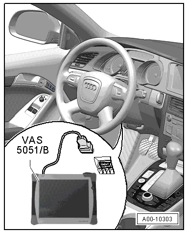
- Connect the Vehicle Diagnostic Tester to the vehicle and guide the diagnostic cable through the open window.
- Turn off all vehicle exterior lamps.
- Close all vehicle door.
Calibration Procedure With or Without A Previous Axle Alignment
- Select the ACC calibration button on the alignment computer.
Follow the Sequence for Adjusting:
1 - The distance between the center of the ACC Reflector Mirror - Audi -VAS6430/3- and the Audi rings must be 120 cm +- 2.5 cm.
Note
- Perform this step if night vision camera was not adjusted earlier.
- If a camera adjustment/calibration was performed earlier, then it is not necessary to reposition the Setting Device Basic Set -VAS6430/1-.
2 - Position the ACC Reflector Mirror - Audi -VAS6430/3- on the right side in front of the Distance Regulation Control Module -J428-,
3 - Adjust the Distance Regulation Control Module -J428-,
4 - Attach the ACC Reflector Mirror, Audi on the opposite side of the calibration beam in front of Distance Regulation Control Module 2 -J850-,
5 - Check the position of the bubble level and of the calibration beam (using the display on the wheel alignment computer) and correct it if necessary,
6 - Adjust the Distance Regulation Control Module 2 -J850-.
Note
Before adjusting the ACC, check both "sensors" and their mounts and attachments for damage, external influences and secure fit. Repair any damaged components. Likewise, check the front bumper cover for damage, cracks and secure fit and service any damaged parts, if necessary.
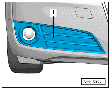
- Remove the right and left air intake grilles -1-. Refer to → Body Exterior; Rep. Gr.63; Rear Bumper; Attachments, Removing and Installing.
- Remove any dirt that may be on the sensor lens.
- Connect the Vehicle Diagnostic Tester to the vehicle. (Guide the diagnostic cable through the door window.)
Process without A Previously Calibrating/Adjusting the Night Vision Camera
- Position the Setting Device Basic Set -VAS6430/1- in distance -A- from the center of the ACC Reflector Mirror - Audi -VAS6430/3- up to the Audi rings.
Note
- Distance -A- = 120 cm +- 2.5 cm, measured between the ACC Reflector Mirror - Audi -VAS6430/3- and the surface of the Audi rings.
- The Setting Device Basic Set -VAS6430/1- must not be moved on the calibration beam.
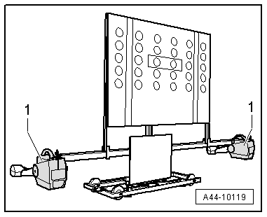
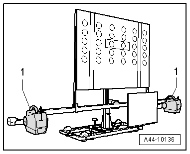
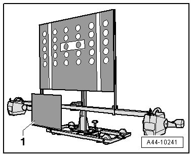
- Mount the front wheel measuring sensors -1- onto the Setting Device Basic Set -VAS6430/1-.
Procedure for All
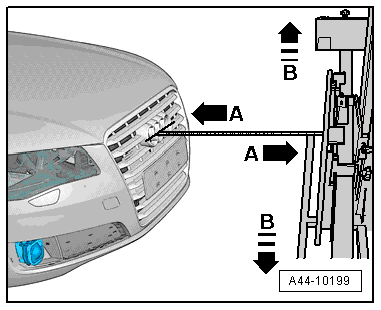
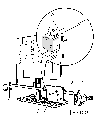
- Install the ACC Reflector Mirror AUDI on the right side next to the vertical slits as illustrated.
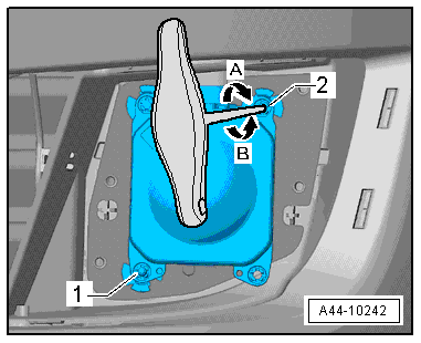
- In area -A-, bring Item -2- on rotary knob into alignment with marking on mirror (number 2 on rotary knob must face toward vehicle).
- Align the Setting Device Basic Set -VAS6430/1- by moving it from side to side -B arrows-.
- Level the bubble levels -A and B- on the Setting Device Basic Set -VAS6430/1- using the adjusting screws -1, 2 and 3-.
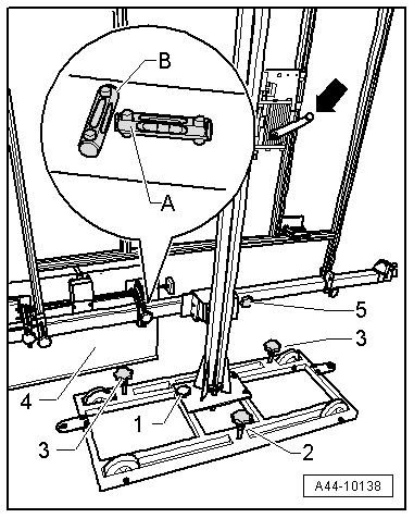
- Adjust the mirror -4- using the crank -arrow- on the Setting Device Basic Set -VAS6430/1- so the laser beam is vertically centered on the sensor lens. Adjust the mirror -4- from side to side on the calibration beam until the laser beam is horizontally centered on the sensor lens.
- Adjust the same front axle individual toe settings using fine adjustment screw -5-.
- The difference between individual toe values must be less than 6' or they must be the same.
- Bring bubbles -2- on measurement sensor -1- into balance.
- Now using the laser beam -3- on the Setting Device Basic Set -VAS6430/1-, check if the laser beam contacts the sensor lens.
Note
- If the laser beam still meets the sensor lens at this step after adjusting the same individual toe values, the Setting Device Basic Set -VAS6430/1- is aligned correctly (positioned).
- If the laser beam does not meet the sensor lens, the Setting Device Basic Set -VAS6430/1- must be aligned again.
- Switch on the Vehicle Diagnostic Tester.
The Vehicle Diagnostic Tester is ready for operation when the operating modes are displayed.
- Turn on the ignition.
- Touch Guided Fault Finding.
- Select in succession:
- Brand
- Type
- Model year
- Version
- Engine Code
- Confirm data entered.
Wait until the Vehicle Diagnostic Tester has checked all the vehicle control module.
- Press the go to button and select "function/component selection".
- Select the corresponding program in "Guided Functions".
Now follow instructions on screen to perform adjustment.
- Use the lower screw -1- and the upper screw -2- to fine adjust the Distance Regulation Control Module -J428- in "Guided Functions".
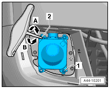
After the Distance Regulation Control Module -J428- has been adjusted successfully, then adjust the Distance Regulation Control Module 2 -J850-.
The procedure for adjusting the Distance Regulation Control Module 2 -J850- is identical to adjusting Distance Regulation Control Module -J428-. To do this, move the ACC Reflector Mirror Audi-1- to the opposite of the of the calibration beam. Refer to → Chapter "Adaptive Cruise Control (ACC), Calibrating".
- Use the lower screw -1- and the upper screw -2- to fine adjust the Distance Regulation Control Module 2 -J850- in "Guided Functions".
 WARNING
The ACC adjustment is confirmed when "output diagnostic test complete" appears in the Vehicle Diagnostic Tester.
- Switch off the ignition.
- Disconnect the Diagnostic Cable connector from Data Link Connector (DLC).
- Disconnect the battery charger. Refer to → Electrical Equipment; Rep. Gr.27; Battery; Battery, Charging.
- Install the air intake grille. Refer to → Body Exterior; Rep. Gr.63; Rear Bumper; Attachments, Removing and Installing.