Audi A6 Typ 4G: Battery, Removing and Installing
Battery, Removing and Installing, Vehicles without High Voltage System
 Note
Note
If the battery is to be replaced, connect the battery charger for battery support mode. Refer to → Electrical Equipment General Information; Rep. Gr.27; Battery, Charging.
Removing
- Turn off the ignition.
- Lift the luggage compartment floor covering by the handle and fold it forward.
- If equipped remove the pressure reservoir and set aside with the lines still attached. Refer to → Suspension, Wheels, Steering; Rep. Gr.43; Air Suspension; Pressure Reservoir, Removing and Installing.
- Remove the vehicle tools.
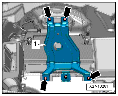
- Remove the bolts -arrows- and remove the bracket -1-.
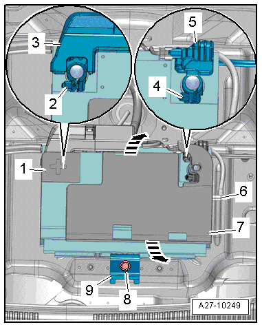
- Remove the battery negative pole cover -7- from the battery in direction of -arrows-.
- Loosen the nut -4- a few turns and disconnect the ground cable from the battery negative pole -5-.
- Remove the cover -1- over the battery positive pole.
- Loosen the nut -2- a few turns and remove the battery positive cable terminal -3- with the main fuse panel from the battery positive pole.
- Remove the hose -6- for the central venting system.
- Remove the bolt -8- from the battery bracket -9-.
- Remove the battery from the battery tray and remove it from the luggage compartment.
 WARNING
Pollution risk.
Battery and sulfuric acid disposal regulations must be followed when disposing of batteries. Refer to → Electrical Equipment General Information; Rep. Gr.27; Battery.
Installing
Note
- Only maintenance-free batteries conforming to standards "TL82506" (from 12/1997) and "VW75073" (from 08/2001) may be installed.
- Batteries from the Audi Parts Program have a bottom strip-adapter for adapting to different grip channels. For information on how to use the base strip adapter, if applicable, see the battery operating instructions.
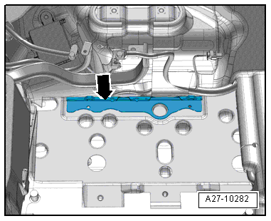
- Install the battery in the battery tray so that the battery clamping strip fits into the strip in the battery tray -arrow-.
- It should no longer be possible to move the battery.
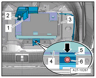
- Install the battery bracket -5-.
- The tab -arrow- on the battery bracket must fit into the opening on the battery clamping strip -4-.
- Tighten the bolt -6- on the battery bracket.
- Connect the hose for the central venting system -3-. Refer to → Electrical Equipment General Information; Rep. Gr.27; Battery.
- Turn off the ignition and all electrical consumers, and connect the battery in the following sequence:
- First connect the battery positive cable terminal -2- to the battery positive pole "+" by hand and tighten the nut.
- Close the cover -1- over the battery positive terminal.
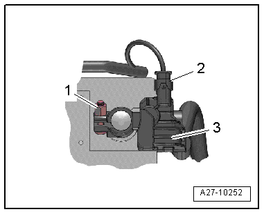
- Disconnect the connector -2- from the Battery Monitoring Control Module -J367--item 3-.
- Connect the battery ground cable terminal to the battery negative pole "-" by hand and tighten the nut -1-.
- Reconnect the connector to the Battery Monitoring Control Module -J367-.
- Make sure the battery is secure after installing it. Refer to → Electrical Equipment General Information; Rep. Gr.27; Battery.
- Install the battery negative pole cover on the battery.
- Install the bracket -1- and tighten the bolts -arrows-.
- After replacing, adapt the battery in "Guided Fault Finding" or "Guided Functions" using the Vehicle Diagnostic Tester.
When the battery is connected, the following steps must be performed:
- Activate the one-touch up/one-touch down power window regulators. Refer to the Owner's Manual.
- Check DTC memories of all control modules and erase "Undervoltage" DTC if necessary using the Vehicle Diagnostic Tester.
Note
After connecting the power supply, the ABS warning lamp may only go out after the vehicle has been driven a few yards.
Battery -A-, Removing and Installing, Vehicles with High Voltage System
DANGER!
Damaged high voltage components may produce dangerously high voltage.
Note the following when working near high voltage components and cables:
- Do not use tools that have sharp edges, that are used for cutting or shaping, or that generate heat, such as welding, soldering, hot air or thermal adhesive equipment.
- Inspect the high voltage components in the area where the work will be performed before starting the procedure.
- Perform a visual inspection of the Electric Drive Power and Control Electronics -JX1-, the Electro-Drive Drive Motor -V141-, the Electrical A/C Compressor -V470- and the high voltage cables when working inside the engine compartment.
- Perform a visual inspection of the high voltage cables and the covers when working on the floor panel.
- Perform a visual inspection of the high voltage cables and the electro-box with the High Voltage System Maintenance Connector -TW- when working in the rear of the vehicle.
- Perform a visual inspection of all of the potential equalization cables.
Note the following when performing the visual inspection:
- None of the components may display any exterior damage.
- The high voltage cable insulation and the potential equalization cables may not be damaged.
- The high voltage cables may not be deformed in any way.
- Each high voltage component muss be labeled with a red warning label.
Removing
- Remove the Auxiliary Battery -A1-. Refer to → Chapter "Auxiliary Battery -A1-, Removing and Installing, Vehicles with High Voltage System".
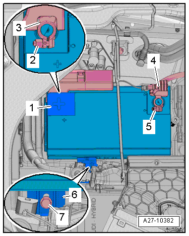
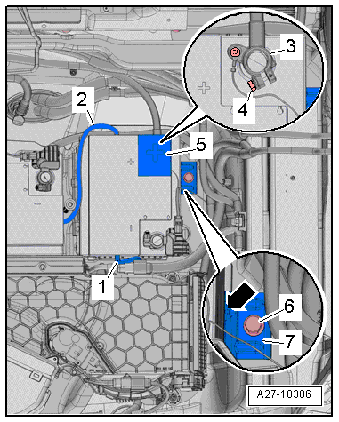
- Loosen the nut -5- several turns and remove the battery ground cable terminal -4- from the battery terminal.
- Open the cover -1- over the battery positive terminal.
- Loosen the nut -2- a few turns and remove the battery positive cable terminal -3- with the Fuse Panel A -SA- from the battery terminal
- Remove the bolt -7- from the battery bracket -6-.
- Pry the battery out of the luggage compartment.
WARNING
Pollution risk.
Battery and sulfuric acid disposal regulations must be followed when disposing of batteries. Refer to → Electrical Equipment General Information; Rep. Gr.27; Battery.
Installing
Install in reverse order of removal. Note the following:
Note
- Only maintenance-free batteries conforming to standards "TL82506" (from 12/1997) and "VW75073" (from 08/2001) may be installed.
- Batteries from the Audi Parts Program have a bottom strip-adapter for adapting to different grip channels. For information on how to use the base strip adapter, if applicable, see the battery operating instructions.
- Install the battery in the battery tray so that the battery clamping strip fits into the strip in the battery tray -arrow-.
- It should no longer be possible to move the battery.
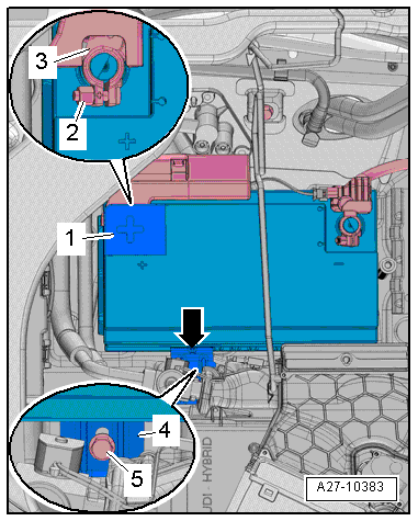
- Mount the battery bracket -4-.
- The tab -arrow- on the battery mounting bracket must fit into the opening on the battery clamping strip.
- Tighten the bolt -5- for the battery bracket.
- Connect the hose for the central venting system. Refer to → Electrical Equipment General Information; Rep. Gr.27; Battery.
- Turn off the ignition and all electrical consumers, and connect the battery in the following sequence:
- First connect the positive battery cable terminal -3- to the battery positive pole "+" by hand and tighten the nut -2-.
- Close the cover -1- over the battery positive terminal.
- Disconnect the connector -2- from the Battery Monitoring Control Module -J367--item 3-.
- Connect the battery ground cable terminal to the battery negative pole "-" by hand and tighten the nut -1-.
- Reconnect the connector to the Battery Monitoring Control Module -J367-.
- Make sure the battery is secure after installing it. Refer to → Electrical Equipment General Information; Rep. Gr.27; Battery.
- Install the Auxiliary Battery -A1-. Refer to → Chapter "Auxiliary Battery -A1-, Removing and Installing, Vehicles with High Voltage System".
- After replacing, adapt the battery in "Guided Fault Finding" or "Guided Functions" using the Vehicle Diagnostic Tester.
When the battery is connected, the following steps must be performed:
- Activate the one-touch up/one-touch down power window regulators. Refer to the Owner's Manual.
- Check DTC memories of all control modules and erase "Undervoltage" DTC if necessary using the Vehicle Diagnostic Tester.
Note
After connecting the power supply, the ABS warning lamp may only go out after the vehicle has been driven a few yards.
Auxiliary Battery -A1-, Removing and Installing, Vehicles with High Voltage System
DANGER!
Damaged high voltage components may produce dangerously high voltage.
Note the following when working near high voltage components and cables:
- Do not use tools that have sharp edges, that are used for cutting or shaping, or that generate heat, such as welding, soldering, hot air or thermal adhesive equipment.
- Inspect the high voltage components in the area where the work will be performed before starting the procedure.
- Perform a visual inspection of the Electric Drive Power and Control Electronics -JX1-, the Electro-Drive Drive Motor -V141-, the Electrical A/C Compressor -V470- and the high voltage cables when working inside the engine compartment.
- Perform a visual inspection of the high voltage cables and the covers when working on the floor panel.
- Perform a visual inspection of the high voltage cables and the electro-box with the High Voltage System Maintenance Connector -TW- when working in the rear of the vehicle.
- Perform a visual inspection of all of the potential equalization cables.
Note the following when performing the visual inspection:
- None of the components may display any exterior damage.
- The high voltage cable insulation and the potential equalization cables may not be damaged.
- The high voltage cables may not be deformed in any way.
- Each high voltage component muss be labeled with a red warning label.
Removing
- Remove the luggage compartment floor. Refer to → Body Interior; Rep. Gr.70; Luggage Compartment Trim Panels; Luggage Compartment Floor Panel, Removing and Installing.
- Remove the battery exhaust air guide. Refer to → Heating, Ventilation, and Air Conditioning; Rep. Gr.87; Battery Cooling Module.
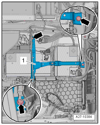
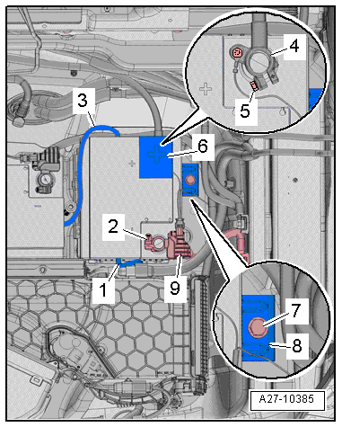
- Remove the bolts -arrows-.
- Remove the bracket -1-.
- Loosen the nut -2- several turns and remove the battery ground cable terminal -9- from the battery terminal.
- Open the cover -6- over the battery positive terminal.
- Turn the nut -5- a few turns and remove the battery positive cable terminal -4- from the battery pole.
- Remove the hoses -1 and 3- for the central venting system.
- Remove the bolt -7- from the battery bracket -8-.
- Pry the battery out of the luggage compartment.
WARNING
Pollution risk.
Battery and sulfuric acid disposal regulations must be followed when disposing of batteries. Refer to → Electrical Equipment General Information; Rep. Gr.27; Battery.
Installing
Install in reverse order of removal. Note the following:
Note
- Only maintenance-free batteries conforming to standards "TL82506" (from 12/1997) and "VW75073" (from 08/2001) may be installed.
- Batteries from the Audi Parts Program have a bottom strip-adapter for adapting to different grip channels. For information on how to use the base strip adapter, if applicable, see the battery operating instructions.
- Install the battery in the battery tray so that the battery clamping strip fits into the strip in the battery tray -arrow-.
- It should no longer be possible to move the battery.
- Mount the battery bracket -7-.
- The tab -arrow- on the battery mounting bracket must fit into the opening on the battery clamping strip.
- Tighten the bolt -6- on the battery bracket.
- Connect the hoses -1 and 2- for the central venting system. Refer to → Electrical Equipment General Information; Rep. Gr.27; Battery.
- Turn off the ignition and all electrical consumers, and connect the battery in the following sequence:
- First connect the positive battery cable terminal -3- to the battery positive pole "+" by hand and tighten the nut -4-.
- Close the cover -5- over the battery positive terminal.
- Disconnect the connector -2- from the Battery Monitoring Control Module 2 -J934--item 3-.
- Connect the battery ground cable terminal to the battery negative pole "-" by hand and tighten the nut -1-.
- Connect the connector again to the Battery Monitoring Control Module 2 -J934-.
- Make sure the battery is secure after installing it. Refer to → Electrical Equipment General Information; Rep. Gr.27; Battery.
- Install the Auxiliary Battery -A1-. Refer to → Chapter "Auxiliary Battery -A1-, Removing and Installing, Vehicles with High Voltage System".
- After replacing, adapt the battery in "Guided Fault Finding" or "Guided Functions" using the Vehicle Diagnostic Tester.
When the battery is connected, the following steps must be performed:
- Activate the one-touch up/one-touch down power window regulators. Refer to the Owner's Manual.
- Check DTC memories of all control modules and erase "Undervoltage" DTC if necessary using the Vehicle Diagnostic Tester.
Note
After connecting the power supply, the ABS warning lamp may only go out after the vehicle has been driven a few yards.
