Audi A6 Typ 4G: Wheel Bearing Housing Bonded Rubber Bushing, Replacing
Wheel Bearing Housing Bonded Rubber Bushing, Replacing, FWD Vehicles
Special tools and workshop equipment required
- Press Plate -VW401-
- Press Plate -VW402-
- Press Piece - Rod -VW408A-
- Press Piece - Rod -VW411-
- Shop Press -VAG1290A-
- Bearing Installer - Wheel Bearing Bushing -T40184-
Removing
- Remove wheel bearing housing. Refer to → Chapter "Wheel Bearing Housing, Removing and Installing, FWD Vehicles".
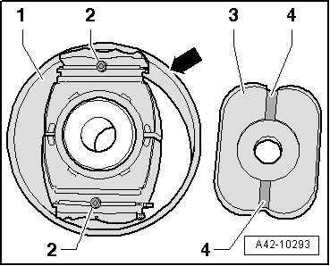
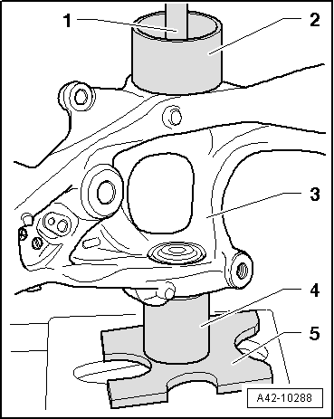
- In order to remove the front rubber bonded bushing, the Bearing Installer - Wheel Bearing Bushing - Pressure Plate -T40184/2--3- must be mounted on the front rubber bonded bushing in such a way so that the lugs -2- fit into the grooves -4-.
- Place the tools on the front bonded rubber bushing and the wheel bearing housing as illustrated.
 Note
Note
When mounting the wheel bearing housing onto the Sleeve -T40184/1- be careful not to damage or push the rubber grommet on the rear rubber bonded bushing.
1 - Press Piece - Rod -VW411-
2 - Bearing Installer - Wheel Bearing Bushing - Pressure Plate -T40184/2-
3 - Wheel bearing housing
4 - Bearing Installer - Wheel Bearing Bushing - Sleeve -T40184/1-. The side with the groove must face the wheel bearing housing. On a bonded rubber bushing with a "positioning tab", this is in the groove on the Bearing Installer - Wheel Bearing Bushing - Sleeve -T40184/1-.
- Press out the front rubber bonded bushing.
Installing
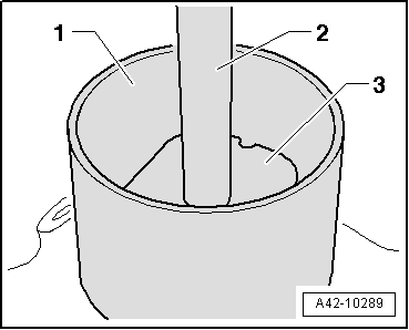
- Place the front bonded rubber bushing in the Bearing Installer - Wheel Bearing Bushing - Sleeve -T40184/3-. The "thin" collar -arrow- must face upward.
- In order to install the front rubber bonded bushing, the Bearing Installer - Wheel Bearing Bushing - Pressure Plate -T40184/2--3- must be mounted on the front rubber bonded bushing in such a way so that the lugs -2- fit into the grooves -4-.
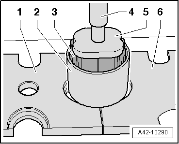
- Press the front rubber bonded bushing all the way onto the thrust plates -1 and 6-.
1 - Press Plate -VW401-. Arrange as illustrated.
2 - Sleeve -T40184/3-
3 - Front bonded rubber bushing
4 - Press Piece - Rod -VW408A-
5 - Bearing Installer - Wheel Bearing Bushing - Pressure Plate -T40184/2-
6 - Press Plate -VW402-. Arrange as illustrated.
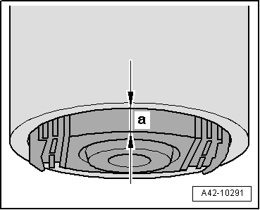
- Then slightly pull apart the thrust plates -1 and 6-.
- Press the front rubber bonded bushing approximately 2 mm out of the Sleeve -T40184/3-.
a = 2 mm
- Remove the Press Piece - Rod -VW408A- and insert the Press Piece - Rod -VW411-.
- Position the wheel bearing housing on the Shop Press -VAG1290A-.
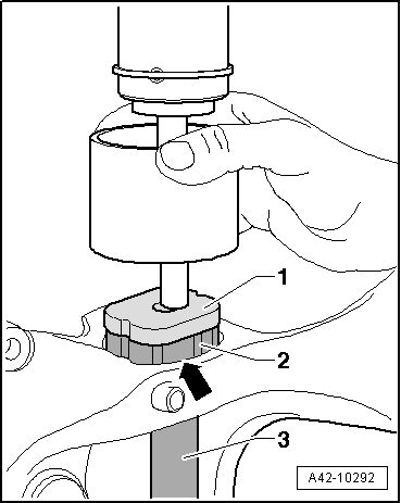
- Mount the front rubber bonded bushing (not shown in the illustration), the pressure plate -3- and the sleeve -1- on the wheel housing bearing.
1 - Sleeve -T40184/3-
2 - Press Piece - Rod -VW411-
3 - Bearing Installer - Wheel Bearing Bushing - Pressure Plate -T40184/2- Pay attention to the installation position of the front rubber bonded bushing.
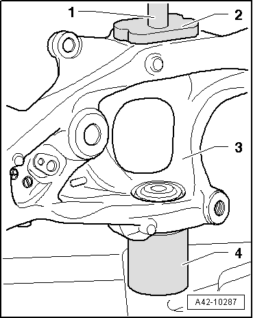
- Place the tools on the front bonded rubber bushing and the wheel bearing housing -3- as illustrated.
Note
When mounting the wheel bearing housing onto the Sleeve -T40184/1- be careful not to damage or push the rubber grommet on the rear rubber bonded bushing.
- Slowly press the front rubber bonded bushing in (not shown in the illustration) until the sleeve -2- can be pulled out at the top.
1 - Press Piece - Rod -VW411-
2 - Sleeve -T40184/3-
3 - Wheel bearing housing
4 - Bearing Installer - Wheel Bearing Bushing - Sleeve -T40184/1-. The side with the groove must face the wheel bearing housing. On a bonded rubber bushing with a "positioning tab", this is in the groove on the Bearing Installer - Wheel Bearing Bushing - Sleeve -T40184/1-.
5 - Press Plate -VW402-
- Slowly press the front rubber bonded bushing -2- so that it is even with the edge -arrow- of the wheel bearing housing.
Note
Ignore Item -3-.
- Install the wheel bearing housing. Refer to → Chapter "Wheel Bearing Housing, Removing and Installing, FWD Vehicles".
Wheel Bearing Housing Bonded Rubber Bushing, Replacing, AWD Vehicles
Special tools and workshop equipment required
- Press Plate -VW401-
- Press Plate -VW402-
- Press Piece - Rod -VW408A-
- Press Piece - Rod -VW411-
- Shop Press -VAG1290A-
- Bearing Installer - Wheel Bearing Bushing -T40184-
Removing
- Remove wheel bearing housing. Refer to → Chapter "Wheel Bearing Housing, Removing and Installing, FWD Vehicles".
- In order to remove the front rubber bonded bushing, the Bearing Installer - Wheel Bearing Bushing - Pressure Plate -T40184/2--3- must be mounted on the front rubber bonded bushing in such a way so that the lugs -2- fit into the grooves -4-.
- Place the tools on the front bonded rubber bushing and the wheel bearing housing as illustrated.
Note
When mounting the wheel bearing housing onto the Sleeve -T40184/1- be careful not to damage or push the rubber grommet on the rear rubber bonded bushing.
1 - Press Piece - Rod -VW411-
2 - Bearing Installer - Wheel Bearing Bushing - Pressure Plate -T40184/2-
3 - Wheel bearing housing
4 - Bearing Installer - Wheel Bearing Bushing - Sleeve -T40184/1-. The side with the groove must face the wheel bearing housing. On a bonded rubber bushing with a "positioning tab", this is in the groove on the Bearing Installer - Wheel Bearing Bushing - Sleeve -T40184/1-.
- Press out the front rubber bonded bushing.
Installing
- Place the front bonded rubber bushing in the Bearing Installer - Wheel Bearing Bushing - Sleeve - T40184/3-. The "thin" collar -arrow- must face upward.
- In order to install the front rubber bonded bushing, the Bearing Installer - Wheel Bearing Bushing - Pressure Plate -T40184/2--3- must be mounted on the front rubber bonded bushing in such a way so that the lugs -2- fit into the grooves -4-.
- Press the front rubber bonded bushing all the way onto the thrust plates -1 and 6-.
1 - Press Plate -VW401-. Arrange as illustrated.
2 - Sleeve -T40184/3-
3 - Front bonded rubber bushing
4 - Press Piece - Rod -VW408A-
5 - Bearing Installer - Wheel Bearing Bushing - Pressure Plate -T40184/2-
6 - Press Plate -VW402-. Arrange as illustrated.
- Then slightly pull apart the thrust plates -1 and 6-.
- Press the front rubber bonded bushing approximately 2 mm out of the Sleeve -T40184/3-.
a = 2 mm
- Remove the Press Piece - Rod -VW408A- and insert the Press Piece - Rod -VW411-.
- Position the wheel bearing housing on the Shop Press -VAG1290A-.
- Mount the front rubber bonded bushing (not shown in the illustration), the pressure plate -3- and the sleeve -1- on the wheel housing bearing.
1 - Sleeve -T40184/3-
2 - Press Piece - Rod -VW411-
3 - Bearing Installer - Wheel Bearing Bushing - Pressure Plate -T40184/2- Pay attention to the installation position of the front rubber bonded bushing.
- Place the tools on the front bonded rubber bushing and the wheel bearing housing -3- as illustrated.
Note
When mounting the wheel bearing housing onto the Sleeve -T40184/1- be careful not to damage or push the rubber grommet on the rear rubber bonded bushing.
- Slowly press the front rubber bonded bushing in (not shown in the illustration) until the sleeve -2- can be pulled out at the top.
1 - Press Piece - Rod -VW411-
2 - Sleeve -T40184/3-
3 - Wheel bearing housing
4 - Bearing Installer - Wheel Bearing Bushing - Sleeve -T40184/1-. The side with the groove must face the wheel bearing housing. On a bonded rubber bushing with a "positioning tab", this is in the groove on the Bearing Installer - Wheel Bearing Bushing - Sleeve -T40184/1-.
5 - Press Plate -VW402-
- Install the front bonded rubber bushing -2- using Bearing Installer - Wheel Bearing Bushing Pressure Plate -T40184/2--1- slowly until it is flush with the edge -arrow- of the wheel bearing housing.
Note
Ignore Item -3-.
- Install the wheel bearing housing. Refer to → Chapter "Wheel Bearing Housing, Removing and Installing, FWD Vehicles".
