Audi A6 Typ 4G: Control Module/Amplifier for Digital Sound System, Removing and Installing
Digital Sound System Control Module -J525-, Removing and Installing, BOSE, RMC, through MY 2014
Special tools and workshop equipment required
- Fiber-Optic Repair Set - Connector Protective Caps -VAS6223/9-.
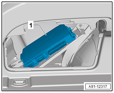
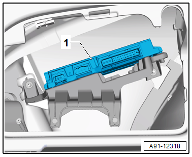
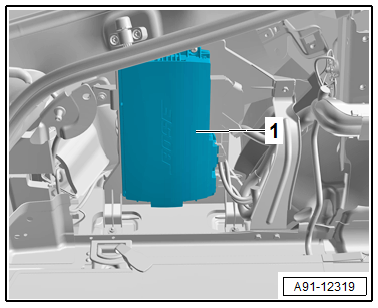
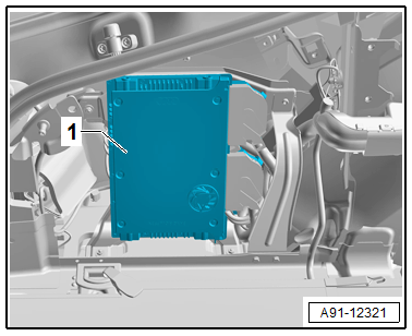
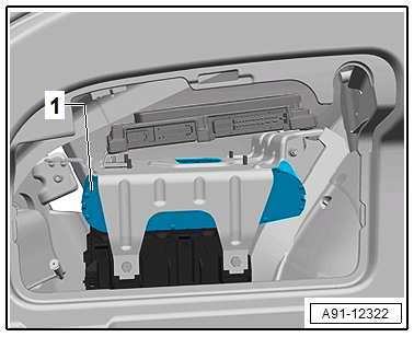
The Digital Sound System Control Module -J525--1- is located behind the left luggage compartment trim panel.
 Note
Note
If replacing the control module, select the "Replace Control Module" function on the Vehicle Diagnostic Tester.
Removing
- Turn off the ignition and all electrical consumers and remove the ignition key.
- Open the left storage compartment in the luggage compartment.
The bracket with the Digital Sound System Control Module -J525- must be removed first.
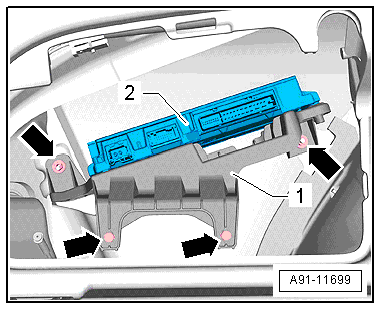
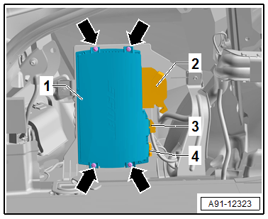
- Release and disconnect the connectors from the Digital Sound System Control Module -J525--2-.
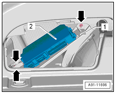
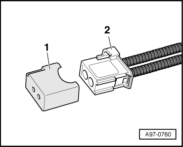
- Insert the Fiber-Optic Repair Set - Connector Protective Caps -VAS6223/9--1- onto the MOST Bus connector -2-.
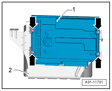
- Remove the nuts -arrows- on the bracket -1- and remove the Digital Sound System Control Module -J525--2- with the bracket -1-.
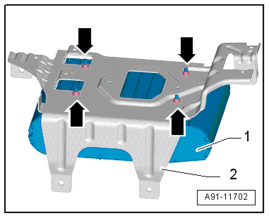
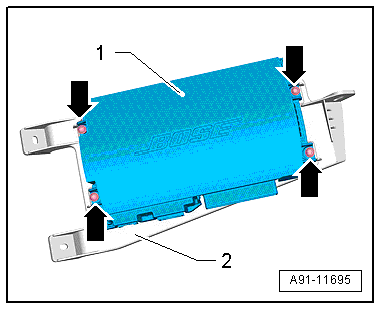
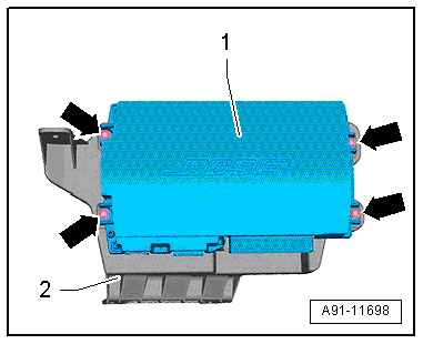
- Remove the screws -arrows- and remove the Digital Sound System Control Module -J525--1- from the bracket -2-.
Installing
- Install in reverse order of removal.
Digital Sound System Control Module -J525-, Removing and Installing, BOSE, MMI, through MY 2014
Special tools and workshop equipment required
- Fiber-Optic Repair Set - Connector Protective Caps -VAS6223/9-.
The Digital Sound System Control Module -J525--1- is located behind the left luggage compartment trim panel.
Note
If replacing the control module, select the "Replace Control Module" function on the Vehicle Diagnostic Tester.
Removing
- Turn off the ignition and all electrical consumers and remove the ignition key.
- Open the left storage compartment in the luggage compartment.
The bracket with the Digital Sound System Control Module -J525- must be removed first.
- Release and disconnect the connectors from the Digital Sound System Control Module -J525--2-.
- Insert the Fiber-Optic Repair Set - Connector Protective Caps -VAS6223/9--1- onto the MOST Bus connector -2-.
- Remove the nuts and screws -arrows- on the bracket -1- and remove the Digital Sound System Control Module -J525--2- with the bracket -1-.
- Remove the screws -arrows- and remove the Digital Sound System Control Module -J525--1- from the bracket -2-.
Installing
- Install in reverse order of removal.
Digital Sound System Control Module -J525-, Removing and Installing, Standard and BOSE, from MY 2015
Special tools and workshop equipment required
- Fiber-Optic Repair Set - Connector Protective Caps -VAS6223/9-.
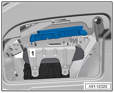
The Digital Sound System Control Module -J525--1- is located behind the left luggage compartment trim panel.
Note
If replacing the control module, select the "Replace Control Module" function on the Vehicle Diagnostic Tester.
Removing
- Turn off the ignition and all electrical consumers and remove the ignition key.
- Open the left storage compartment in the luggage compartment.
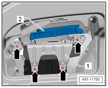
- Release and disconnect the connectors -2 and 3- and -4- from the Digital Sound System Control Module -J525--1-.
- Insert the Fiber-Optic Repair Set - Connector Protective Caps -VAS6223/9--1- onto the MOST Bus connector -2-.
- Remove the screws -arrows- on the bracket and remove the Digital Sound System Control Module -J525--1-.
Installing
- Install in reverse order of removal.
Digital Sound System Control Module -J525-, Removing and Installing, Bang & Olufsen, through MY 2014
Special tools and workshop equipment required
- Fiber-Optic Repair Set - Connector Protective Caps -VAS6223/9-.
The Digital Sound System Control Module -J525--1- is located behind the left luggage compartment trim panel.
Note
If replacing the control module, select the "Replace Control Module" function on the Vehicle Diagnostic Tester.
Removing
- Turn off the ignition and all electrical consumers and remove the ignition key.
- Open the left storage compartment in the luggage compartment.
The bracket with the Digital Sound System Control Module -J525- must be removed first.
- Release and disconnect the connectors from the Digital Sound System Control Module -J525--2-.
- Insert the Fiber-Optic Repair Set - Connector Protective Caps -VAS6223/9--1- onto the MOST Bus connector -2-.
- Remove the nuts and screws -arrows- on the bracket -1- and remove the Digital Sound System Control Module -J525--2- with the bracket -1-.
- Remove the screws -arrows- and remove the Digital Sound System Control Module -J525--1- from the bracket -2-.
Installing
- Install in reverse order of removal.
Digital Sound System Control Module -J525-, Removing and Installing, Bang & Olufsen, from MY 2015
Special tools and workshop equipment required
- Fiber-Optic Repair Set - Connector Protective Caps -VAS6223/9-.
The Digital Sound System Control Module -J525--1- is located behind the left luggage compartment trim panel.
Note
If replacing the control module, select the "Replace Control Module" function on the Vehicle Diagnostic Tester.
Removing
- Turn off the ignition and all electrical consumers and remove the ignition key.
- Remove the left luggage compartment side trim panel. Refer to → Body Interior; Rep. Gr.70; Luggage Compartment Trim Panels; Luggage Compartment Side Trim Panel, Removing and Installing.
The bracket with the Digital Sound System Control Module -J525- must be removed first.
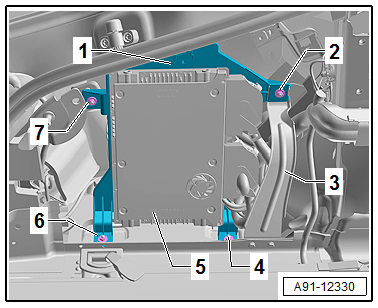
- Remove the nuts -4, 6 and 7- and the screw -2- on the bracket -1-.
- Remove the brace -3-.
- Pivot the Digital Sound System Control Module -J525--5- with the bracket -1- into the luggage compartment.
- Release and disconnect the connectors from the Digital Sound System Control Module -J525--5-.
- Insert the Fiber-Optic Repair Set - Connector Protective Caps -VAS6223/9--1- onto the MOST Bus connector -2-.
- Remove the Digital Sound System Control Module -J525--5- with the bracket -1-.
- Remove the screws -arrows- and remove the Digital Sound System Control Module -J525--1- from the bracket -2-.
Installing
- Install in reverse order of removal.
Digital Sound System Control Module 2 -J787-, Removing and Installing, Bang & Olufsen, through MY 2014
Special tools and workshop equipment required
- Fiber-Optic Repair Set - Connector Protective Caps -VAS6223/9-.
The Digital Sound System Control Module 2 -J787--1- is located behind the left luggage compartment trim panel and under the Digital Sound System Control Module -J525-.
Note
If replacing the control module, select the "Replace Control Module" function on the Vehicle Diagnostic Tester.
Removing
- Turn off the ignition and all electrical consumers and remove the ignition key.
- Open the left storage compartment in the luggage compartment.
The bracket with the Digital Sound System Control Module -J525- must be removed first.
- Release and disconnect the connectors from the Digital Sound System Control Module -J525--2-.
- Insert the Fiber-Optic Repair Set - Connector Protective Caps -VAS6223/9--1- onto the MOST Bus connector -2-.
- Remove the nuts and screws -arrows- on the bracket -1- and remove the Digital Sound System Control Module -J525--2- with the bracket -1-.
The Digital Sound System Control Module -J525- covers the nuts on the Digital Sound System Control Module 2 -J787-.
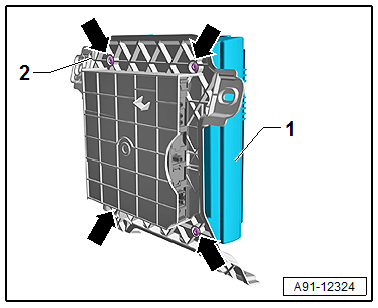
- Remove the screws -arrows- and remove the Digital Sound System Control Module -J525--1- from the bracket -2-.
- Remove the nuts -arrows- on the bracket -2- and remove the Digital Sound System Control Module 2 -J787--1- from the bracket -2-.
Installing
- Install in reverse order of removal.