Audi A6 Typ 4G: Disposal
Front Shock Absorbers, Venting and Emptying
A - Venting through Drill Holes
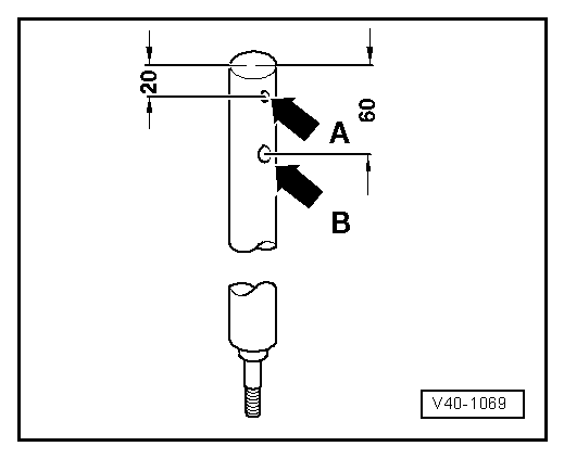
- Secure gas-filled shock absorber vertically in vise, with piston rod facing down.
 WARNING
Wear protective eyewear while drilling.
- Drill a 3 mm hole -arrow A- through the shock absorber outer tube.
 Note
Note
Gas escapes when drilling.
- Continue drilling until the tube inside is drilled through (approximately 25 mm deep).
- Drill a second 6 mm hole -arrow B- through the outer and inner shock absorber tubes.
- Hold the shock absorber over an appropriate container for catching oil and move the piston rod repeatedly through the entire stroke until no more oil flows out.
B - Open with Pipe Cutter
WARNING
Wear protective eyewear when drilling or sawing.
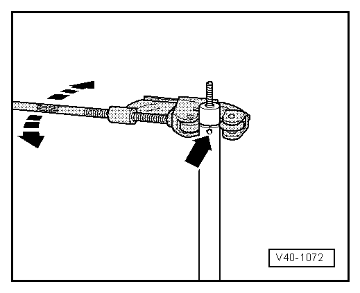
- Drill a 3 mm hole -arrow- through the shock absorber outer tube or saw through the tube wall.
Note
Gas escapes when drilling or sawing.
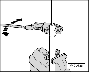
- Attach a pipe cutter (for example, 150/3 Stahlwille Express) as shown in illustration, and cut through outer shock absorber tube.
- Pull the piston rod upward, hold the inner shock absorber tube in place with pliers and push it downward so that it remains in the outer shock absorber tube when the piston rod is slowly raised.
- Remove the piston rod from the shock absorber inner tube
- Empty the shock absorber tube.
Rear Shock Absorbers, Venting and Emptying
A - Venting through Drill Holes
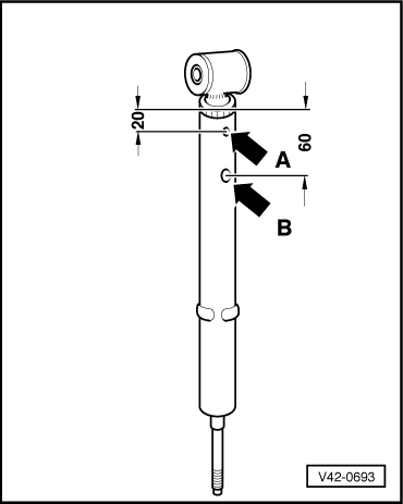
- Secure gas-filled shock absorber vertically in vise, with piston rod facing down.
WARNING
Wear protective eyewear while drilling.
- Drill a 3 mm hole -arrow A- through the shock absorber outer tube.
Note
Gas escapes when drilling.
- Continue drilling until the tube inside is drilled through (approximately 25 mm deep).
- Drill a second 6 mm hole -arrow B- through the outer and inner shock absorber tubes.
- Hold the shock absorber over an appropriate container for catching oil and move the piston rod repeatedly through the entire stroke until no more oil flows out.
B - Open with Pipe Cutter
WARNING
Wear protective eyewear when drilling or sawing.
- Drill a 3 mm hole through the shock absorber outer tube or saw through the tube wall.
Note
Gas escapes when drilling or sawing.
- Attach a pipe cutter (for example, 150/3 Stahlwille Express) as shown in illustration, and cut through outer shock absorber tube.
- Pull the piston rod upward, hold the inner shock absorber tube in place with pliers and push it downward so that it remains in the outer shock absorber tube when the piston rod is slowly raised.
- Remove the piston rod from the shock absorber inner tube
- Empty the shock absorber tube.
Front Air Suspension Strut, Emptying
Special tools and workshop equipment required
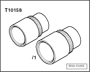
- Pressure Retention Socket -T10158/1-
- Remove the front air spring shock absorber. Refer to → Chapter "Suspension Strut, Removing and Installing, Air Spring Damper".
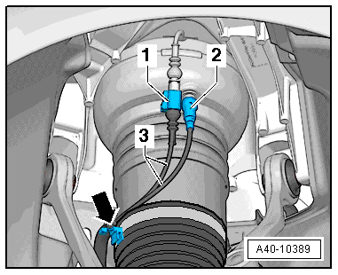
- Slowly open the residual pressure retaining valve -2- on the front air spring shock absorber and allow the air pressure to escape.
Note
The air spring shock absorber is shown in its installed position.
- Dispose of the air spring damper.
Pressure Reservoir, Emptying
Special tools and workshop equipment required
- Vehicle Diagnostic Tester
Procedure
- Remove the air suspension system. Refer to → Chapter "System, Venting or Filling".
- Remove the pressure reservoir. Refer to → Chapter "Pressure Reservoir, Removing and Installing".
- Dispose of the pressure reservoir.
Special Tools
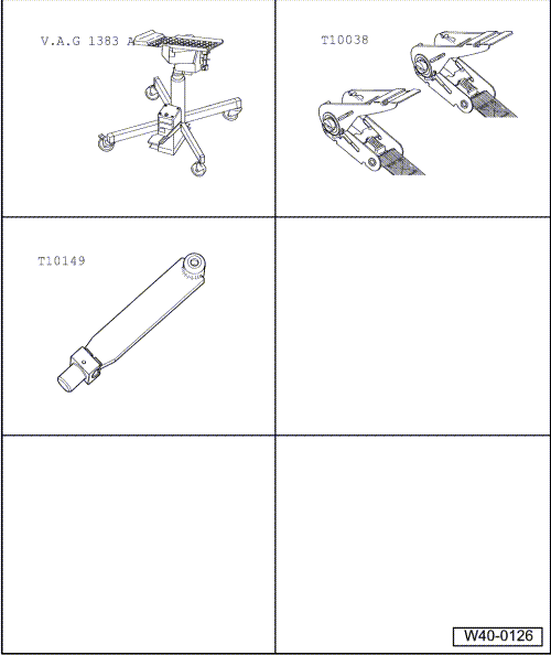
Special tools and workshop equipment required
- Engine and Gearbox Jack -VAS6931-
- Tensioning Strap -T10038-
- Engine/Gearbox Jack Adapter - Wheel Hub Support -T10149-
- Pressure Retention Socket -T10158/1-