Audi A6 Typ 4G: Compressor/Multi-contour Seat Control Module, Removing and Installing
Multi-contour Seat Compressors, Removing and Installing, through 08/2012
Removing
 WARNING
- Follow all Safety Precautions when working with pyrotechnic components. Refer to → Chapter "Pyrotechnic Components Safety Precautions".
- Before handling pyrotechnic components (for example, disconnecting the connector), the person handling it must "discharge static electricity". This can be done by touching the door striker, for example.
- Remove the front seat. Refer to → Chapter "Front Seat, Removing and Installing".
- Fasten the front seat on the Engine/Transmission Holder - Seat Repair Fixture -VAS6136-. Refer to → Chapter "Front Seat, Mounting on Fixture for Seat Repair".
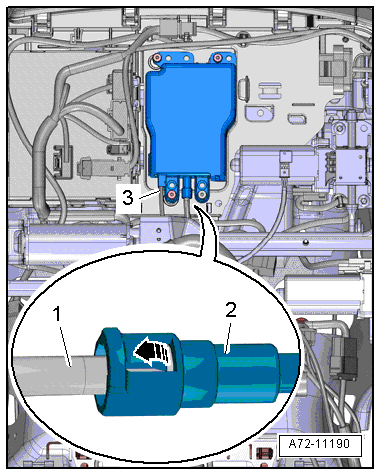
- Disconnect the connector -3-.
- Carefully release the retainer -arrow- and remove the pneumatic line -1- from the compressor -2-.
- Free up pneumatic line to the compressor.
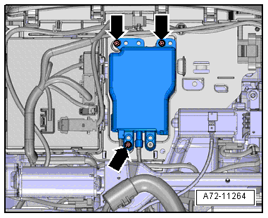
- Remove the nuts -arrows- and compressor.
Installing
WARNING
- Follow all Safety Precautions when working with pyrotechnic components. Refer to → Chapter "Pyrotechnic Components Safety Precautions".
- Before handling pyrotechnic components (for example, connecting the connector), the person handling it must "discharge static electricity". This can be done by touching the door striker, for example.
- Observe all measures when installing the front seat. Refer to → Chapter "Front Seat, Removing and Installing".
Install in reverse order of removal. Note the following:
 Note
Note
- The rubber-metal compress mount must not be installed under tension or twisted.
- Therefore, brace the metal plate of the rubber-metal mount with pliers while the nut is tightened. Do not damage rubber-metal mount while doing so.
Installation notes, for example tightening specifications, replacing components. Refer to → Chapter "Overview - Pneumatic System, Compressor".
Multi-contour Seat Compressor Bonded Rubber Bushing, Removing and Installing, through 08/2012
Special tools and workshop equipment required
- Drill
- Protective eyewear
Removing
WARNING
- Follow all Safety Precautions when working with pyrotechnic components. Refer to → Chapter "Pyrotechnic Components Safety Precautions".
- Before handling pyrotechnic components (for example, disconnecting the connector), the person handling it must "discharge static electricity". This can be done by touching the door striker, for example.
- Remove front trim bracket, compressor and Multi-contour seat control module. Refer to → Chapter "Front Seat Trim Bracket/Compressor/Control Module, Removing and Installing, Multi-contour Seat".
- Remove the compressor. Refer to → Chapter "Multi-contour Seat Compressors, Removing and Installing, through 08/2012".
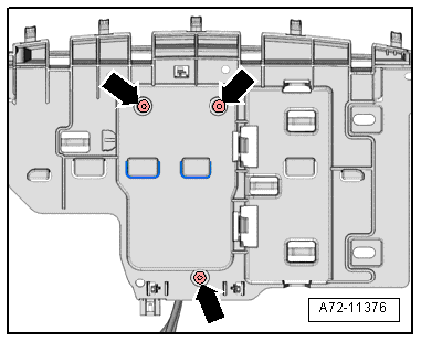
WARNING
Danger of eye injury.
Wear protective eyewear.
- Drill out the rivets -arrows- and remove the Multi-contour seat compressor bonded rubber bushing.
Installing
WARNING
- Follow all Safety Precautions when working with pyrotechnic components. Refer to → Chapter "Pyrotechnic Components Safety Precautions".
- Before handling pyrotechnic components (for example, connecting the connector), the person handling it must "discharge static electricity". This can be done by touching the door striker, for example.
- Observe all measures when installing the front seat. Refer to → Chapter "Front Seat, Removing and Installing".
Install in reverse order of removal. Note the following:
Note
- The rubber-metal compress mount must not be installed under tension or twisted.
- Therefore, first bolt all rubber-metal mounts to the compressor (refer to → Chapter "Overview - Pneumatic System, Compressor") and then rivet them.
Multi-contour Seat Control Module, Removing and Installing, through 08/2012
Removing
- Remove the backrest cover. Refer to → Chapter "Backrest Cover, Removing and Installing, Multi-contour Seat".
- For reinstallation, mark pneumatic lines at the separating point with a waterproof permanent marker.
Note
- Depending on the version, the check valve installed as a separate component or is integrated in the Front Passenger Multi-contour Seat Control Module -J872-/Driver Multi-contour Seat Control Module -J873-.
- Original replacement parts have an integrated check valve and restrictor and the connection for the restrictor has been removed.
- Remove the external check valve if installing a Multi-contour seat control module that contains a check valve. Refer to the Parts Catalog.
- Original replacement parts are delivered with short sections of line to which pneumatic lines with line connectors are connected.
- Before disconnecting the pneumatic lines, transfer the length of the sections of line from the original spare part to the part to be removed and disconnect at exactly this point.
Note
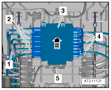
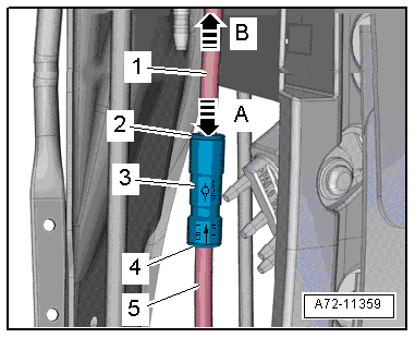
Version with Separate Check Valve.
- Press the circlip -2- in direction of -arrow A- and simultaneously remove pneumatic line -1--arrow B-.
- Repeat the procedure with the circlip -4- and pneumatic line -5-.
- Remove the check valve -3-.
Continuation for all Versions:
- Disconnect the connector -5-.
- Version with an integrated check valve: disconnect the pneumatic line. Refer to → Chapter "Pneumatic Lines, Disconnecting and Connecting".
- Push the Multi-contour front seat control module -3- up -arrow- and remove it.
- Disconnect the pneumatic lines -2 and 4- at the multi-contour front seat control module. Refer to → Chapter "Pneumatic Lines, Disconnecting and Connecting".
1 - Check Valve, Depending on the Version
Installing
Install in reverse order of removal. Note the following:
Installation notes, for example tightening specifications, replacing components. Refer to → Chapter "Overview - Pneumatic System, Backrest".