Audi A6 Typ 4G: Module Carrier with Air Cushions for Lumbar Support, Removing and Installing
Module Carrier with Air Cushions for Lumbar Support, Removing and Installing, through 08/2012
Special tools and workshop equipment required
- Drill
- Protective eyewear
Removing
- Remove the backrest cover. Refer to → Chapter "Backrest Cover, Removing and Installing, Multi-contour Seat".
- Remove backrest blower fan. Refer to → Chapter "Front Backrest Fan, Removing and Installing".
- Remove the backrest cover with the backrest cushion. Refer to → Chapter "Backrest Cover and Cushion, Removing and Installing, Multi-contour Seat through 08/2012".
 WARNING
Danger of eye injury.
Wear protective eyewear.
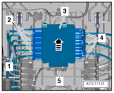
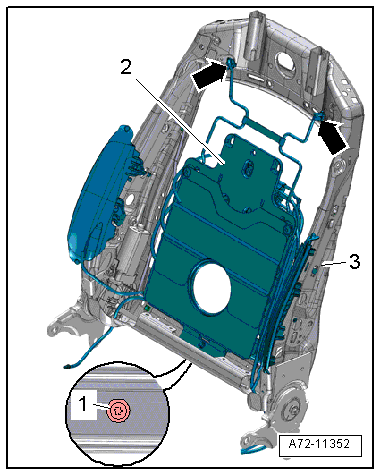
- Drill out the rivet -1- from the pulsation damper -2-.
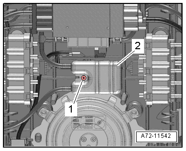
- Disconnect harness connector -5- and free up electrical wire at the module carrier.
- Push the front multi-contour seat control module -3- up slightly for the detachment at the module carrier -arrow-.
- Disconnect the pneumatic lines -4- to the lumbar support air cushions.
 Note
Note
Ignore items -1 and 2-.
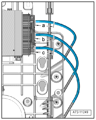
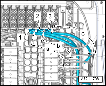
- Disconnect pneumatic lines to the lumbar support air cushions at the following points (refer to → Chapter "Pneumatic Lines, Disconnecting and Connecting"):
- a - 40 mm
- b - 40 mm
- c - 40 mm
- Set aside the multi-contour front seat control module together with the remaining connected pneumatic lines.
Note
- Original replacement parts are delivered with short sections of line to which pneumatic lines with line connectors are connected.
- Before disconnecting the pneumatic lines, transfer the length of the sections of line from the original spare part to the part to be removed and disconnect at exactly this point.
- Cut cable ties, free up wiring harness and free up pneumatic lines on the lumbar support module carrier.
- Remove the bolt -1-.
- Move the module carrier -2- with the lumbar support air cushions toward the front, disengage is from the backrest frame -3--arrows- and remove it.
Installing
Install in reverse order of removal. Note the following:
Installation notes, for example tightening specifications, replacing components. Refer to → Chapter "Overview - Pneumatic System, Backrest".
Module Carrier, Air Cushion for Lumbar Support, Removing and Installing, from 09/2012
Removing
- Remove the backrest cover. Refer to → Chapter "Backrest Cover, Removing and Installing, Multi-contour Seat".
- Remove backrest blower fan. Refer to → Chapter "Front Backrest Fan, Removing and Installing".
- Remove the backrest cover with the backrest cushion. Refer to → Chapter "Backrest Cover and Cushion, Removing and Installing, Multi-contour Seat from 09/2012".
- Before disconnecting, mark the pneumatic line assignments to the connections at the valve block using a waterproof permanent marker.
Note
If a repair is required, the pneumatic lines are not disconnected at the connections, but are disconnected using the following described procedure. Refer to → Chapter "Pneumatic Lines, Disconnecting and Connecting".
- Disconnect the pneumatic lines -1, 2 and 3- from the lumbar support air cushions at the following locations:
- a - 120 mm
- b - 120 mm
- c - 120 mm
- Free up the pneumatic lines from the lumbar support air cushions.
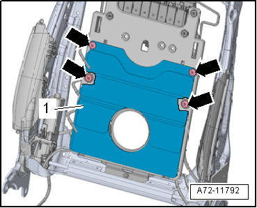
- Remove the expanding rivets -arrows- and remove the air cushion -1-.
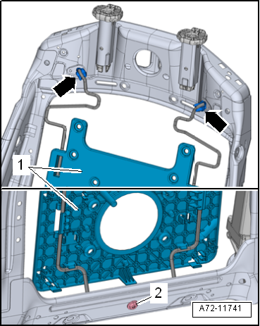
- Remove the bolt -2-.
- Move the module carrier -1- for the lumbar support air cushions forward and remove them from the backrest frame -arrows-.
Installing
Install in reverse order of removal. Note the following:
Installation notes, for example tightening specifications, replacing components. Refer to → Chapter "Overview - Pneumatic System, Backrest".
Driver Seat Switch Module 2 -E667 -/Front Passenger Seat Switch Module 2 -E668-, Removing and Installing
Special tools and workshop equipment required
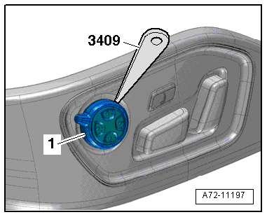
- Trim Removal Wedge -3409-
Removing
- Remove the trim on the sill side. Refer to → Chapter "Seat Side Trim on Sill Panel Side/Front Seat Trim, Removing and Installing, Multi-contour Seat".
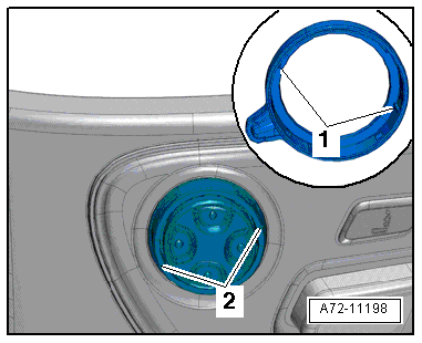
- Carefully unclip the rocker -1- from the switch module using the Trim Removal Wedge -3409-.
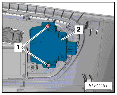
- Remove bolts -1- and switch module -2-.
Installing
Install in reverse order of removal. Note the following:
- Insert trim with the tabs -1- in the grooves -2- on the switch module and press on it until it engages audibly.
Installation notes, for example tightening specifications, replacing components. Refer to → Chapter "Overview - Seat Pan, Seat Adjustment Actuator/Switch".