Audi A6 Typ 4G: Control Arm, Removing and Installing
Special tools and workshop equipment required
- Torque Wrench 1332 40-200Nm -VAG1332-
- Engine and Gearbox Jack -VAS6931-
- Engine/Gearbox Jack Adapter - Wheel Hub Support -T10149-
- Puller - Ball Joint -T40010A-
- Torque Wrench 1332 Insert - Ring Wrench - 21mm -VAG1332/7-
- For a vehicle with air suspension Vehicle Diagnostic Tester
Removing
- Place the vehicle on a hoist. Refer to → Chapter "Raising and Lowering with Open and Closed Air Suspension System".
- Remove the wheel. Refer to → Chapter "Wheels and Tires".
- Remove the noise insulation. Refer to → Body Exterior; Rep. Gr.66; Noise Insulation; Noise Insulation, Removing and Installing.
- Remove the nut -2-.
- Disconnect the bolting -3-.
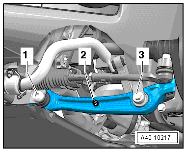
- Remove the nut -1- from the tie rod end joint pin -2- until it is flush with the joint pin threads. Counterhold when loosening.
To Protect Thread, Screw Nut On Pin A Few Turns
- Remove the tie rod end from the wheel bearing housing using the Puller - Ball Joint -T40010A-. Remove the nut.
 Note
Note
Make sure that both puller lever arms are parallel to each other when using greatest force, adjust if necessary.
- In order to not damage the joints of the upper control arms, the wheel bearing housing must be braced against too strong rebound using the Engine and Gearbox Jack -VAS6931-, for example.
- Install Engine/Gearbox Jack Adapter - Wheel Hub Support -T10149- with wheel bolt on wheel hub.
- Support the wheel bearing housing over the Engine/Gearbox Jack Adapter - Wheel Hub Support -T10149- using the Engine and Gearbox Jack -VAS6931-.
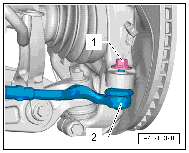
- Disconnect the threaded connection -1-.
Note
To remove the bolt -1-, turn the steering gear all the way to the left or right depending on the side of the vehicle.
- Guide the control arm out and tilt it back.
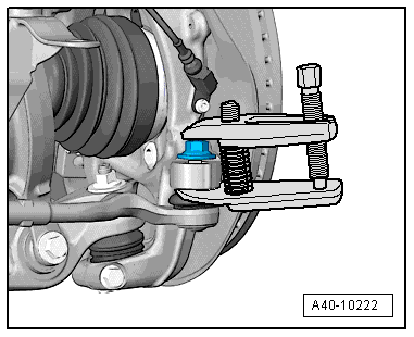
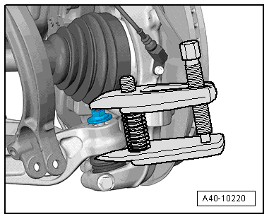
- Remove the nut from the ball joint pins just enough so it is flush with the joint pin threads. Counterhold when loosening.
- Press the joint pin of the ball joint off the conical seat using the Puller - Ball Joint -T40010A-.
Note
- Make sure that both puller lever arms are parallel to each other when using greatest force, adjust if necessary.
- Be careful not to damage CV boot in the process!
- In order to not damage the joints of the upper control arms, the wheel bearing housing must be braced against too strong rebound using the Engine and Gearbox Jack -VAS6931-, for example.
- Remove the nut from linkage stub of track control arm.
- Remove track control arm.
Installing
Install in reverse order of removal. Note the following:
Note
- Bonded rubber bushings have a limited range of motion. Only tighten suspension bolts when vehicle is in curb weight or control position.
- Lift the wheel bearing into the control position. Refer to → Chapter "Wheel Bearing in Control Position, Lifting Vehicles with Air Suspension" or → Chapter "Wheel Bearing in Curb Weight, Lifting Vehicles with Coil Spring".
- When tightening the threaded connection -1-, the control arm must be pressed toward the inside of the vehicle.
- Remove the adhesive residue from the ball joint stub thread.
- On vehicles with automatic head lamp range control, perform headlamp basic setting. Refer to → Electrical Equipment; Rep. Gr.94; Headlamp; Headlamp, Adjusting.
- If the Level Control Sensor was removed and installed or if the linkage was loosened, the control position must be programmed again by starting the correct program on the Vehicle Diagnostic Tester in Guided Functions.
- If the control position was reprogrammed on vehicles with lane assist, the Camera Control Module -J852- must be calibrated again. Refer to → Chapter "Driver Assistance Systems Front Camera, Calibrating".
- Install the wheel. Refer to → Chapter "Wheels and Tires".
- To determine if an axle alignment is required, see Table. Refer to → Chapter "Evaluating Need for Axle Alignment".
Guide Link, Removing and Installing
Special tools and workshop equipment required
- Torque Wrench 1332 40-200Nm -VAG1332-
- Torque Wrench 1332 Insert - Ring Wrench - 21mm -VAG1332/7-
- Engine and Gearbox Jack -VAS6931-
- Engine/Gearbox Jack Adapter - Wheel Hub Support -T10149-
- Puller - Ball Joint -T40042-
- For a vehicle with air suspension Vehicle Diagnostic Tester
Removing
- Place the vehicle on a hoist. Refer to → Chapter "Raising and Lowering with Open and Closed Air Suspension System".
- Remove the wheel. Refer to → Chapter "Wheels and Tires".
- Remove the noise insulation. Refer to → Body Exterior; Rep. Gr.66; Noise Insulation; Noise Insulation, Removing and Installing.
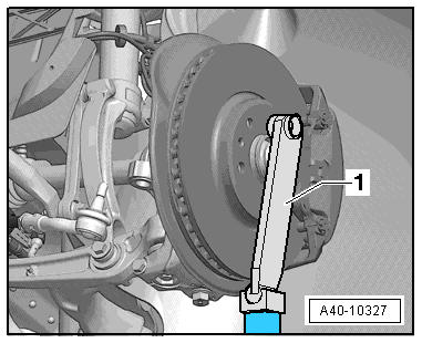
- Secure the brake disc with a wheel bolt.
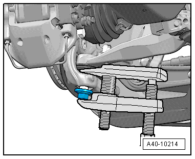
- Remove the nut from the guide link joint pins enough so it is flush with the joint pin threads. Counterhold the joint pins if necessary.
- Press the guide link joint pin off the conical seat using the Puller - Ball Joint -T40042-.
Note
- Be careful not to damage CV boot in the process!
- Make sure that both puller lever arms are parallel to each other when using greatest force.
Note
- Be careful not to damage CV boot in the process!
- Make sure that both puller lever arms are parallel to each other when using greatest force.
- Prevent the ball joint puller from falling down.
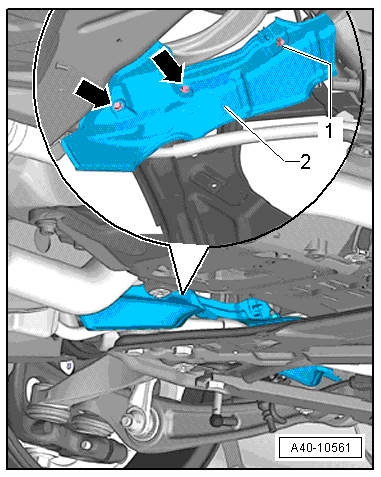
- Remove the heat shield -2-. Refer to → Chapter "Subframe Heatshield, Removing and Installing".
- Disconnect the threaded connection -1-.
- Remove the guide link from the subframe.
Installing
Install in reverse order of removal. Note the following:
- If the guide link is installed again, remove the locking compound from the ball joint threads first.
- First tighten the bolts/nuts on components with bonded rubber bushings by hand.
Note
- Bonded rubber bushings have a limited range of motion. Only tighten suspension bolts when vehicle is in curb weight or control position.
- Lift the wheel bearing into the control position. Refer to → Chapter "Wheel Bearing in Control Position, Lifting Vehicles with Air Suspension" or → Chapter "Wheel Bearing in Curb Weight, Lifting Vehicles with Coil Spring".
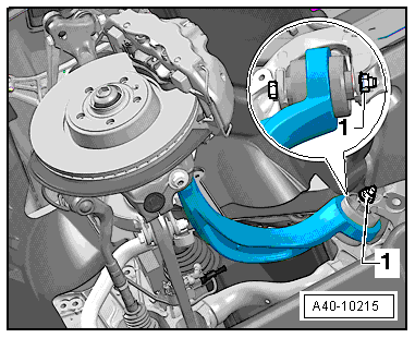
- When tightening the threaded connection -1-, the guide link must be pressed toward the inside of the vehicle.
- Install the wheel. Refer to → Chapter "Wheels and Tires".
- Place vehicle on wheels. Refer to → Chapter "Raising and Lowering with Open and Closed Air Suspension System".
- To determine if an axle alignment is required, see Table. Refer to → Chapter "Evaluating Need for Axle Alignment".
