Audi A6 Typ 4G: Ball Joint, Removing and Installing
Special tools and workshop equipment required
- Torque Wrench 1332 40-200Nm -VAG1332-
- Torque Wrench 1332 Insert - Ring Wrench - 21mm -VAG1332/7-
- Puller - Ball Joint -T40010A-
- For a vehicle with air suspension Vehicle Diagnostic Tester
Removing
- Remove the control arm. Refer to → Chapter "Control Arm, Removing and Installing".
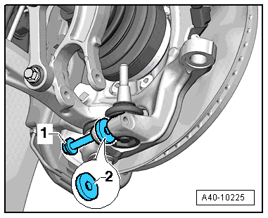
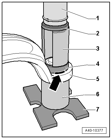
- Remove the bolt -1-.
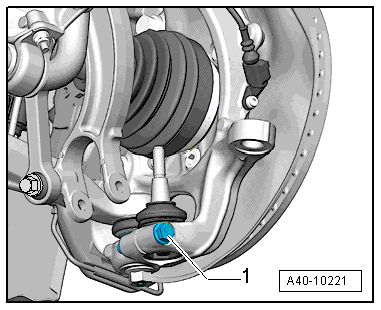
- Insert a washer or something similar -2- into the wheel bearing housing slot. The washer, or something similar, must the be exact same width as the slot.
- Install the bolt -1- until it touches the back of the washer.
- Side the wheel bearing housing slot by installing the bolt -1- further (one half turn).
- Remove the ball joint from the wheel bearing housing.
Installing
Install in reverse order of removal. Note the following:
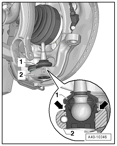
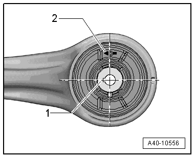
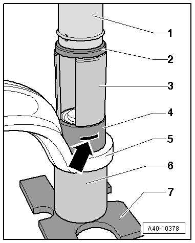
- Install the ball joint -1- into the wheel bearing housing -2- as far as the contact surface -arrows-.
 Note
Note
If the ball joint -1- is not inserted up to the contact surface -arrows- then the threaded connection on the wheel bearing housing -2- could get damaged.
- Install the control arm. Refer to → Chapter "Control Arm, Removing and Installing".
- Install the wheel. Refer to → Chapter "Wheels and Tires".
- To determine if an axle alignment is required, see Table. Refer to → Chapter "Evaluating Need for Axle Alignment".
Guide Link Bonded Rubber Bushing, Removing and Installing
Special tools and workshop equipment required
- Press Plate -VW402-
- Press Piece - Multiple Use -VW412-
- Press Piece - Split Tube -VW463/2-
- Bearing Installer - Wheel Bearing -3144-
- Shop Press -VAG1290A-
- Installation Lubricant (1:20 thinned with water). For allocation. Refer to the Parts Catalog.
Pressing Out Bonded Rubber Bushing
- The guide link is removed. Refer to → Chapter "Guide Link, Removing and Installing"
- Mark the upper and lower installed position -arrow- on the bonded rubber bushing -4-.
Use a water-proof marker.
- Order the special tools as illustrated.
1 - Workshop Press -VAG1290A- punch
2 - Press Piece - Multiple Use -VW412-
3 - Press Piece - Split Tube -VW463/2-
4 - Bonded rubber bushing
5 - Guide link
6 - Bearing Installer - Wheel Bearing -3144-
7 - Press Plate -VW402-
- Remove the bonded rubber bushing -4- from the guide link -5-.
Note
Hold the guide link steady when removing/installing the bonded rubber bushing.
Installing Bonded Rubber Bushing
- Transfer the marking of the press-in depth from the old bonded rubber bushing to the new one.
- Lightly coat the new bonded rubber bushing with installation lubricant. Refer to the Parts Catalog.
Bonded Rubber Bushing Installed Position
The groove on the inner core -1- is on the steering axle and faces the inside of the guide link.
The arrow -2- faces the inside of the guide link.
- Install the bonded rubber bushing -4- in the guide link -5-. Pay attention to the installed position
- Order the special tools as illustrated.
1 - Workshop Press -VAG1290A- punch
2 - Press Piece - Multiple Use -VW412-
3 - Press Piece - Split Tube -VW463/2-
4 - Bonded rubber bushing
5 - Guide link
6 - Bearing Installer - Wheel Bearing -3144-
7 - Press Plate -VW402-
Note
Do not tilt the bonded rubber bushing when installing it.
- Install the bonded rubber bushing -4- in the guide link -5-.
- Pay close attention to the marking -arrow-.
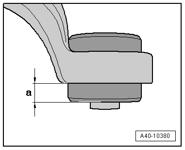
- Check the depth -a- of the bonded rubber bushing inside the guide link.
Dimension -a- = 18 mm.
- If dimension -a- has not been reached, then press the bonded rubber bushing again.
- Install the guide link. Refer to → Chapter "Guide Link, Removing and Installing".