Audi A6 Typ 4G (2011–2018) Workshop Manual / Chassis / Suspension, Wheels, Steering / Front Suspension / Overview - Wheel Bearing
Audi A6 Typ 4G: Overview - Wheel Bearing
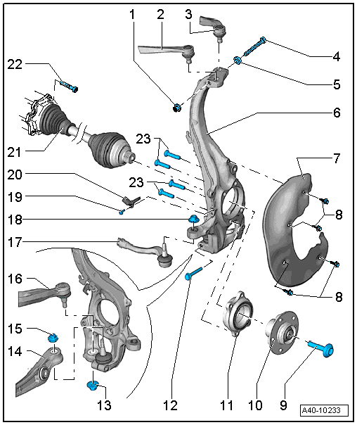
1 - Nut
- 40 Nm
- Always replace if removed
2 - Upper Front Control Arm
3 - Upper Rear Control Arm
4 - Bolt
- Always replace if removed
5 - Washer
6 - Wheel Bearing Housing
- Removing and installing. Refer to → Chapter "Wheel Bearing Housing, Removing and Installing".
7 - Brake Shield
8 - Bolt
- For the tightening specification. Refer to → Brake System;
9 - Bolt
- 200 Nm +180º turn
- Replace after each removal. Refer to → Chapter "Drive Axle General Information".
- Before installing, clean the threads in the CV joint with a tap.
10 - Wheel Hub
- Removing and installing. Refer to → Chapter "Wheel Bearing Unit, Servicing".
11 - Wheel Bearing
- Wheel bearing unit, removing and installing. Refer to → Chapter "Wheel Bearing Unit, Removing and Installing".
- Removing and installing. Refer to → Chapter "Wheel Bearing Unit, Servicing".
 Caution
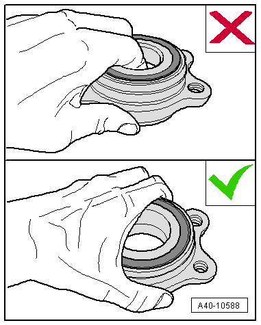
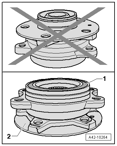
Avoid contaminating with dirt and damaging the seal when lifting, setting down/storing. Refer to → Fig. "Avoid Contaminating with Dirt and Damaging the Seal When Lifting, Setting Down/Storing.".
12 - Bolt
- 40 Nm
- Always replace if removed
13 - Nut
- 140 Nm
- Always replace if removed
- After loosening threaded connection of guide control arm to wheel bearing housing, adhesive residue must be removed on thread of linkage stub.
14 - Control Arm
15 - Nut
- M12: 120 Nm
- M14: 140 Nm
- There are different versions. For allocation. Refer to the Parts Catalog.
- Always replace if removed
- After loosening threaded connection on the ball joint to the wheel bearing housing, adhesive residue must be removed on thread of linkage stub.
16 - Guide Link
17 - Tie Rod End
18 - Nut
- Tightening specification. Refer to → Chapter "Overview - Steering Gear, Steering Gear with Tie Rods"
- Always replace if removed
19 - Bolt
- Tightening specification. Refer to → Brake System; Rep. Gr.45.
20 - Wheel Speed Sensor
21 - drive axle
22 - Bolt
- M10 70 Nm
- Always replace if removed
23 - Cap Bolts
- 80 Nm +90º turn
- Always replace if removed
Avoid Contaminating with Dirt and Damaging the Seal When Lifting, Setting Down/Storing.
- The wheel bearing -1- must always face up.
- Always set the wheel bearing unit down on the wheel hub -2-.
- Never reach into the inside when lifting the wheel bearing.
- Hold the wheel bearing only on the outside.