Audi A6 Typ 4G: Control Module and Hydraulic Unit
Overview - Control Module and Hydraulic Unit
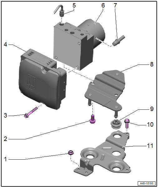
1 - Nut
- 9 Nm
2 - Bolt
- 20 Nm
3 - Bolt
- 4.5 Nm
4 - ABS Control Module -J104-
- Component Location:
- Vehicles without high-voltage system. Refer to → Fig. " ABS Control Module -J104-/ABS Hydraulic Unit -N55- component location - Vehicles without high-voltage system".
- Vehicles with high-voltage system. Refer to → Fig. " ABS Control Module -J104-/ABS Hydraulic Unit -N55- component location - Vehicles with high-voltage system".
- Control module, separating from hydraulic unit. Refer to → Chapter "Control Module, Separating from Hydraulic Unit".
- Control module, attaching to hydraulic unit. Refer to → Chapter "Control Module, Installing on Hydraulic Unit".
5 - Brake Line
- Tightening specification. Refer to → Chapter "Separating Points".
- Do not change the bending shape.
6 - ABS Hydraulic Unit -N55-
- Component Location:
- Vehicles without high-voltage system. Refer to → Fig. " ABS Control Module -J104-/ABS Hydraulic Unit -N55- component location - Vehicles without high-voltage system".
- Vehicles with high-voltage system. Refer to → Fig. " ABS Control Module -J104-/ABS Hydraulic Unit -N55- component location - Vehicles with high-voltage system".
- Removing and installing. Refer to → Chapter "ABS Control Module -J104-/ABS Hydraulic Unit -N55-, Removing and Installing".
 Caution
The pump motor must not be separated from the hydraulic unit.
7 - Brake Line
- Do not change the bending shape.
- Tightening specification. Refer to → Chapter "Separating Points".
8 - Bracket
9 - Buffer
10 - Bolt
- 9 Nm
11 - Bracket
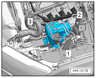
ABS Control Module -J104-/ABS Hydraulic Unit -N55- component location - Vehicles without high-voltage system
The hydraulic unit -2- with the control module -3- and electric connection -1- is located inside the engine compartment on the left front side under the coolant expansion tank.
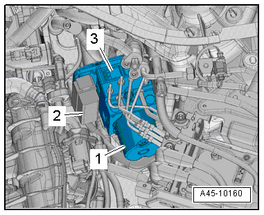
ABS Control Module -J104-/ABS Hydraulic Unit -N55- component location - Vehicles with high-voltage system
The hydraulic unit -2- with the control module -3- and electric connection -1- is located inside the engine compartment on the left front side under the coolant expansion tank.
ABS Control Module -J104-
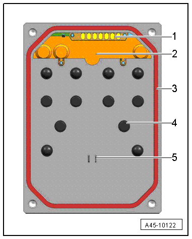
1 - Pressure Sensor Contact
- Do not touch the contacts
- The illustration depends on the model
2 - Pressure Sensor
- Must not be changed or damaged
- Cannot be replaced
- The illustration depends on the model
3 - Seal
- Must not be pulled out or raised up
- Cannot be replaced
4 - Valve Body
- Must not be damaged or bent
- Do not use any tools
5 - Pump Motor Contact
- Must not be damaged or bent
ABS Control Module -J104-/ABS Hydraulic Unit -N55-, Removing and Installing
ABS Control Module -J104-/ABS Hydraulic Unit -N55-, Removing and Installing, Vehicles without High-Voltage System
Special tools and workshop equipment required
- Vehicle Diagnostic Tester
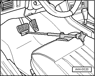
- Brake Pedal Actuator -VAG1869/2-.
- Container from the Brake Charger/Bleeder Unit -VAS5234-
- Plugs from the Assembly Part Set -5Q0698311-
 Note
Note
If the ABS Control Module -J104-/ABS Hydraulic Unit -N55- is being replaced, select the "Replace" function for the ABS Control Module -J104-/ABS Hydraulic Unit -N55- on the Vehicle Diagnostic Tester, Guided Functions.
1 - M10 Plugs
2 - M12 Plugs
Removing
- Switch off the ignition.
- Insert the Brake Pedal Actuator -VAG1869/2- between the brake pedal and driver seat. Press the brake pedal down at least 60 mm.
Note
By doing this, the valves in the brake master cylinder are closed and the brake fluid reservoir does not run empty.
 WARNING
Risk of skin irritation.
To prevent skin contact with brake fluid, wear chemical resistant safety gloves.
- Remove the protective cap -3- from the bleed screw -1- on the left front caliper.
- Connect the container hose -2- as shown in the illustration.
- Open the bleed screw to reduce the pressure in the brake system.
- Close the bleed screw and remove the container.
- Repeat the procedure on the left rear brake caliper.
Note
Do not remove the Brake Pedal Actuator -VAG1869/2-.
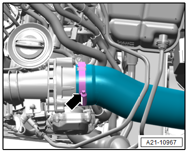
Vehicles with 3.0L TDI engine:
- Loosen the hose clamp -arrow- and remove the air duct hose.
Continuation for All Vehicles:
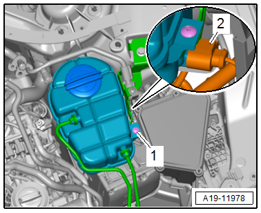
- Remove the bolt -1- and the coolant expansion tank.
- Disconnect the connector -2- and move the coolant expansion tank with the coolant hoses still connected to the side.
Note
The installation position on a 3.0L TDI engine is shown.
- Remove the nuts -arrows- and free up the coolant pipe from the longitudinal member.
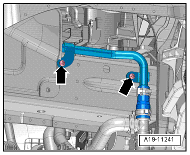
- To protect against escaping brake fluid, place a lint-free rag in the area under the control module and hydraulic unit.
- Mark the brake lines for installation later.
- Remove the brake lines from the brackets.
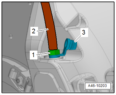
- Remove all brake lines form the hydraulic unit -2-.
Caution
There is a risk of damaging the brake lines.
Do not bend the brake lines near the hydraulic unit.
- Immediately seal brake lines and threaded holes with plugs from the Assembly Part Set -5Q0698311-.
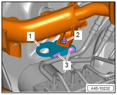
- Release the connector -1- and remove from the control module -3-.
Note
- Make sure that no brake fluid enters the control module connector housing. This could lead to contact corrosion and thereby cause the system to fail.
- Clean a dirty connector housing thoroughly with compressed air.
Vehicles with 3.0L TDI engine
- Remove the nut -2-.
Continuation for All Vehicles:
- Remove the bolts -3- and the bracket -1-.
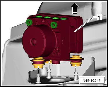
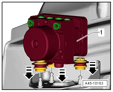
- Remove the ABS Hydraulic Unit -N55--1- with ABS Control Module -J104- and bracket upward in the direction of the -arrow- and remove it from the engine compartment.
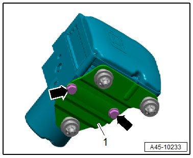
Remove the bolts -arrows- and the bracket -1-.
Caution
There is a risk of destroying the hydraulic unit.
The pump motor may not be separated from the ABS Hydraulic Unit -N55-.
Note
- Only the ABS Control Module -J104- can be replaced individually. Refer to → Chapter "Control Module, Separating from Hydraulic Unit".
- A new ABS Control Module -J104- can be installed on the old hydraulic unit.
- An old ABS Control Module -J104- cannot be installed on a new hydraulic unit.
- If the ABS Hydraulic Unit -N55- is faulty it can only be replaced together with the ABS Control Module -J104-.
Installing
Install in reverse order of removal and note the following:
- Press the ABS Hydraulic Unit -N55- with the ABS Control Module -J104- and bracket on the pins in the engine compartment in the direction of the -arrow-.
- The ABS Hydraulic Unit -N55- with the ABS Control Module -J104- must be seated on all bolts.
Note
- Only remove the plugs on the new hydraulic unit if the corresponding brake line is installed.
- If the plugs are removed too early from the hydraulic unit, brake fluid can escape and the unit may not be sufficiently filled or adequately bled.
- When installing the hydraulic unit, make sure the rubber bushing is not pushed out of the bracket.
- Remove the plugs from the new hydraulic unit.
Note
For better assembly, first insert all the brake lines into the hydraulic unit and then tighten them.
- Insert all the brake lines.
- Tighten all the brake lines.
- After securing brake lines to hydraulic unit, perform output diagnostic test mode using the Vehicle Diagnostic Tester.
Note
It can be determined in output diagnostic test mode, if the line connections were switched.
- Press the brake lines into the brackets.
- Connect the connector to the bottom of the coolant expansion tank.
- Tighten the coolant expansion tank with attached coolant lines to the bracket.
- Remove the Brake Pedal Actuator -VAG1869/2-.
- Bleed the brake system. Refer to → Chapter "Hydraulic System, Standard Bleeding".
- If the ABS Control Module -J104-/ABS Hydraulic Unit -N55- is being replaced, select the "Replace" function for the ABS Control Module -J104-/ABS Hydraulic Unit -N55- on the Vehicle Diagnostic Tester in Guided Functions.
WARNING
Risk of accident!
Make sure the brakes are working correctly before driving the vehicle for the first time.
Control Module, Separating from Hydraulic Unit
Special tools and workshop equipment required
- Torque Screwdriver -VAG1624- 1-5 Nm with external TORX socket E6
- ESD Work Surface -VAS6613-
Control Modules, Replacing
Replace the control module:
- If the Vehicle Diagnostic Tester has determined that the control module is faulty "Control Module Faulty".
- If there is visible damage to the control module housing or to the connector.
Caution
A control module that was removed cannot be attached to a different hydraulic unit.
Note
- Before removing the control module, read out the DTC memory and print out the error code if necessary.
- The control module and the hydraulic unit can be separated.
- The ABS Hydraulic Unit -N55- with the ABS Control Module -J104- must be removed in order to separate the control module and the hydraulic unit.
The replacement should only be done by trained personnel with qualified technical training.
- Only the new parts in the repair kit may be used.
- Only new bolts may be used for attaching the control module to the hydraulic unit.
- The seal on the control module must not be pulled out or raised up.
- The seal on the control module cannot be replaced.
- Blowing the control module or hydraulic unit out with compressed air is not permitted.
- The valve coils inside the control module cannot be readjusted.
- The valve coils inside the control module cannot be replaced.
- The pressure sensor must not be changed or damaged.
- The pressure sensor cannot be replaced.
- The sensor housing must not be under any mechanical load.
- No measurements may be performed on the contacts in the control module.
- No measurements may be performed on the contacts in the hydraulic unit.
- The valve bodies inside the hydraulic unit must not be damaged or bent.
- The contacts cannot be replaced.
- Using contact sprays on the contacts and pressure sensor are not permitted.
- Make sure there are no foreign objects between the control module and the hydraulic unit.
Procedure
Caution
Only separate the ABS Control Module -J104- from the ABS Hydraulic Unit -N55- when they are removed.
- Remove the hydraulic unit. Refer to → Chapter "ABS Control Module -J104-/ABS Hydraulic Unit -N55-, Removing and Installing, Vehicles without High-Voltage System".
Note
The ESD Work Surface -VAS6613- has sufficient grounding to protect against an electrostatic discharge.
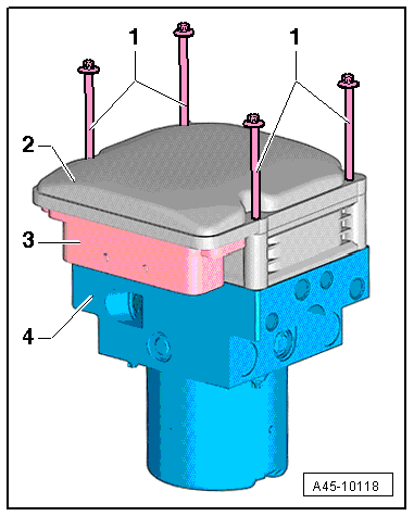
- Place the hydraulic unit with the control module on the ESD Work Surface -VAS6613-.
- The control module -2- faces up and the hydraulic unit -4- with the pump motor and connector -3- faces down.
- Remove the bolts -1- and dispose of them.
- Carefully remove the control module upward holding it vertically.
Note
Be careful not the hook the valve coils when removing them otherwise the valve coils could get stuck on the mount.
Caution
There is a risk of destroying the hydraulic unit.
- Cover the open hydraulic unit. Protect the hydraulic unit, the sealing surfaces, the valve bodies and the pressure sensor from dirt and getting damaged.
- Do not use battery voltage to check the pump motor otherwise contact surfaces could get burned.
- Protect the contact surfaces on the pressure sensor against mechanical damage and electrostatic discharge. The ESD Work Surface -VAS6613- grounds the technician sufficiently to protect against overcharging components.
Control Module, Installing on Hydraulic Unit
Procedure
Note
Replace the bolts after removing them.
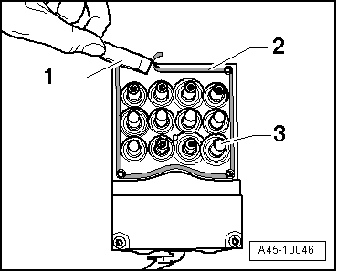
- Clean the sealing surface on the hydraulic unit -2- with a plastic scraper -1-.
- The valve bodies -3- must not be damaged or bent.
Caution
Risk of malfunction.
- The sealing surface on the hydraulic unit must have a clean, even surface.
- Replace the hydraulic unit if the sealing surface or contact tags are damaged.
- The seal on the control module cannot be replaced.
- The seal on the control module must not be pulled out or raised up.
Note
- Do not use aggressive cleaning agents (use the cleaning agent supplied).
- Check the sealing surface for damage (visual check).
Caution
There is a risk of destroying the ABS control module.
- Moisture and dirt particles must not enter the inside of the control module.
- Do not use compressed air to blow out the control module or hydraulic unit.
- Protect the control module from bumps or impact. A control module that has fallen to the ground can no longer be used.
- Check the valve body inside the hydraulic unit for damage.
Caution
Risk of malfunction.
The hydraulic unit cannot be used again if the valve body is damaged or bent.
- The hydraulic unit -4- with the pump motor and the connector -3- faces down.
- Mount the control module on the hydraulic unit carefully from the top with the valve coils hanging.
Note
Be careful not to bend the valve coils.
- Install the bolts (do not tighten) until the control module touches the hydraulic unit evenly.
- Tighten the bolts diagonally.
After tightening, check:
- if all the bolts have made contact,
- if the control module and hydraulic unit are touching all the way around.
- Install the hydraulic unit. Refer to → Chapter "ABS Control Module -J104-/ABS Hydraulic Unit -N55-, Removing and Installing".
After replacing the control module and bleeding the brake system:
- Select the "Replace" function for the ABS Control Module -J104-/ABS Hydraulic Unit -N55- using the Vehicle Diagnostic Tester in Guided Functions.
- All the ESP warning lamps must go out.
WARNING
Risk of accident!
Make sure the brakes are working correctly before driving the vehicle for the first time.
